 |
am2zzw00012612
DTC P2002:00 [SKYACTIV-D 1.5]
id0102q2150200
Details On DTCs
|
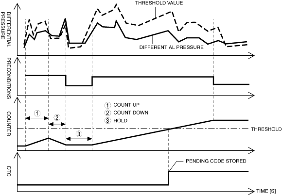
DESCRIPTION |
Diesel particulate filter function decreased |
|
|---|---|---|
|
DETECTION CONDITION
|
Determination conditions
|
• The difference in the pressure before and after passing the diesel particulate filter of less than the specified value is detected for 2s.
|
|
Preconditions
|
• All of the following conditions are met for 2s:
|
|
|
Drive cycle
|
• 2
|
|
|
Self test type
|
• CMDTC self test
|
|
|
Sensor used
|
• Exhaust gas pressure sensor No.1
• Exhaust gas pressure sensor No.2 etc.
|
|
|
FAIL-SAFE FUNCTION
|
• Not applicable
|
|
|
VEHICLE STATUS WHEN DTCs ARE OUTPUT
|
• Check engine light is illuminated
|
|
|
POSSIBLE CAUSE
|
• Exhaust gas leakage from exhaust system
• Pipe between exhaust gas pressure sensor No.2 and catalytic converter (diesel particulate filter) restriction and/or damaged or improper routing
• Exhaust gas pressure sensor No.2 malfunction
• Exhaust gas pressure sensor No.1 malfunction
• Catalytic converter (diesel particulate filter) or diesel particulate filter malfunction (deformation, damage)
• PCM malfunction
|
|
System Wiring Diagram
Function Explanation (DTC Detection Outline)
am2zzw00012612
|
Repeatability Verification Procedure
PID Item/Simulation Item Used In Diagnosis
Function Inspection Using M-MDS
|
STEP |
INSPECTION |
ACTION |
|
|---|---|---|---|
|
1
|
PURPOSE: VERIFY RELATED SERVICE INFORMATION AVAILABILITY
• Verify related Service Information availability.
• Is any related Service Information available?
|
Yes
|
Perform repair or diagnosis according to the available Service Information.
• If the vehicle is not repaired, go to the next step.
|
|
No
|
Go to the next step.
|
||
|
2
|
PURPOSE: IDENTIFY TRIGGER DTC FOR FREEZE FRAME DATA
• Is the DTC P2002:00 on FREEZE FRAME DATA?
|
Yes
|
Go to the next step.
|
|
No
|
Go to the troubleshooting procedure for DTC on FREEZE FRAME DATA.
(See DTC TABLE [SKYACTIV-D 1.5].)
|
||
|
3
|
PURPOSE: RECORD FREEZE FRAME DATA/SNAPSHOT DATA AND DIAGNOSTIC MONITORING TEST RESULTS TO UTILIZE WITH REPEATABILITY VERIFICATION
• Record the FREEZE FRAME DATA/snapshot data and DIAGNOSTIC MONITORING TEST RESULTS (misfire related) on the repair order.
|
—
|
Go to the next step.
|
|
4
|
PURPOSE: VERIFY RELATED PENDING CODE AND/OR DTC
• Switch the ignition off, then ON (engine off).
• Perform the Pending Trouble Code Access Procedure and DTC Reading Procedure.
• Are any other PENDING CODEs and/or DTCs present?
|
Yes
|
Go to the applicable PENDING CODE or DTC inspection.
(See DTC TABLE [SKYACTIV-D 1.5].)
Go to the troubleshooting procedure to perform the procedure from Step 1.
|
|
No
|
Go to the troubleshooting procedure to perform the procedure from Step 1.
|
||
Troubleshooting Diagnostic Procedure
Function Inspection Using M-MDS
|
STEP |
INSPECTION |
ACTION |
|
|---|---|---|---|
|
1
|
PURPOSE: INSPECT EXHAUST SYSTEM FOR LEAKAGE
• Visually inspect for exhaust gas leakage from the exhaust system.
• Is there any malfunction?
|
Yes
|
Repair or replace the malfunctioning part according to the inspection results, then go to Step 5.
|
|
No
|
Go to the next step.
|
||
|
2
|
PURPOSE: INSPECT EXHAUST GAS PRESSURE SENSOR NO.2 RELATED PIPE
• Visually inspect the exhaust gas pressure sensor No.2 related pipe for restriction and damaged.
• Is there any malfunction?
|
Yes
|
Repair or replace the malfunctioning part according to the inspection results, then go to Step 5.
|
|
No
|
Go to the next step.
|
||
|
3
|
PURPOSE: INSPECT EXHAUST GAS PRESSURE SENSOR NO.2
• Reconnect all disconnected connectors.
• Inspect the exhaust gas pressure sensor No.2.
• Is there any malfunction?
|
Yes
|
Replace the exhaust gas pressure sensor No.2, then go to Step 5.
|
|
No
|
Go to the next step.
|
||
|
4
|
PURPOSE: INSPECT EXHAUST GAS PRESSURE SENSOR NO.1
• Reconnect all disconnected connectors.
• Inspect the exhaust gas pressure sensor No.1.
• Is there any malfunction?
|
Yes
|
Replace the exhaust gas pressure sensor No.1, then go to the next step.
|
|
No
|
Catalytic converter (diesel particulate filter) or diesel particulate filter can be considered the cause.
• Replace the catalytic catalytic converter (diesel particulate filter), then go to the next step.
|
||
|
5
|
PURPOSE: PERFORM DTC INSPECTION AND VERIFY IF MALFUNCTIONING PART IS PCM
• Always reconnect all disconnected connectors.
• Clear the DTC from the PCM memory using the M-MDS.
• Implement the repeatability verification procedure.
• Perform the DTC Reading Procedure.
• Is the same DTC present?
|
Yes
|
Repeat the inspection from Step 1.
• If the malfunction recurs, replace the PCM.
Go to the next step.
|
|
No
|
Go to the next step.
|
||
|
6
|
VERIFY AFTER REPAIR PROCEDURE
• Perform the “AFTER REPAIR PROCEDURE”.
• Are any DTCs present?
|
Yes
|
Go to the applicable DTC inspection.
(See DTC TABLE [SKYACTIV-D 1.5].)
|
|
No
|
DTC troubleshooting completed.
|
||