ELECTRIC VARIABLE VALVE TIMING ACTUATOR, HYDRAULIC VARIABLE VALVE TIMING ACTUATOR REMOVAL/INSTALLATION [SKYACTIV-G 1.3, SKYACTIV-G 1.5]
id0110q3126900
SKYACTIV-G 1.3, SKYACTIV-G 1.5 (with 4-1 exhaust system)
-
Warning
-
• A hot engine can cause severe burns. Turn off the engine and wait until it is cool before servicing.
-
Caution
-
• Do not disassemble the hydraulic variable valve timing actuator because they are precision units.
• If the camshaft is rotated with the timing chain removed and the piston at the top dead center position, the valve may contact the piston and the engine could be damaged. When rotating the camshaft with the timing chain removed, rotate it after lowering the piston from the top dead center position.
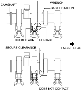
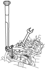
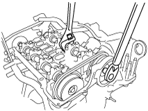
• When rotating the camshaft using a wrench on the cast hexagon, the wrench may contact the rocker arm and damage the rocker arm. To prevent damage to the rocker arm when holding the camshaft on the cast hexagon, use a wrench on the rear side of the engine as shown in the figure to secure a clearance between the cam.
-
Note
-
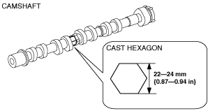
• Width at the cast hexagon of the camshaft is
22—24 mm {0.87—0.94 in}.
1. Disconnect the negative battery cable. (See NEGATIVE BATTERY CABLE DISCONNECTION/CONNECTION.)
2. Remove the plug hole plate. (See PLUG HOLE PLATE REMOVAL/INSTALLATION [SKYACTIV-G 1.3, SKYACTIV-G 1.5].)
3. Remove the ignition coil.(See IGNITION COIL/ION SENSOR REMOVAL/INSTALLATION [SKYACTIV-G 1.3, SKYACTIV-G 1.5].)
4. Remove the cylinder head cover. (See TIMING CHAIN REMOVAL/INSTALLATION [SKYACTIV-G 1.3, SKYACTIV-G 1.5].)
5. Remove in the order indicated in the table.
6. Install in the reverse order of removal.
7. Start the engine and inspect the following:
-
|
1
|
Oil shower pipe
|
|
2
|
Timing chain
|
|
3
|
Chain guide (No.1)
|
|
4
|
Exhaust camshaft sprocket
|
|
5
|
OCV
|
|
6
|
Hydraulic variable valve timing actuator and intake camshaft component
|
|
7
|
OCV oil filter
|
|
8
|
Hydraulic variable valve timing actuator
|
Timing chain removal note
1. Release the tension on the timing chain using the following procedure:
-
Note
-
• Release the tension on the timing chain by securing the timing chain tensioner arm through the service hole on the engine front cover.
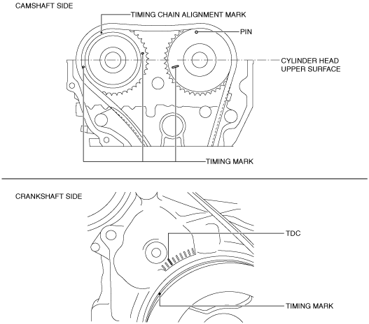
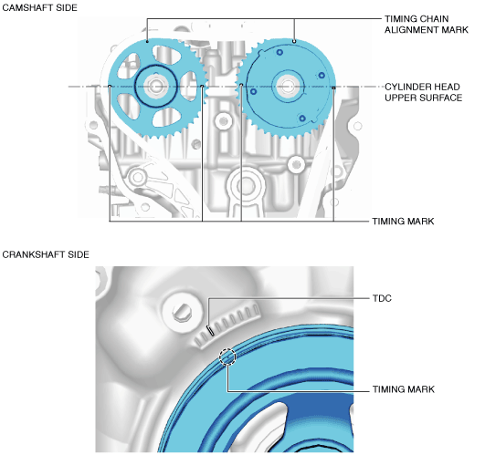
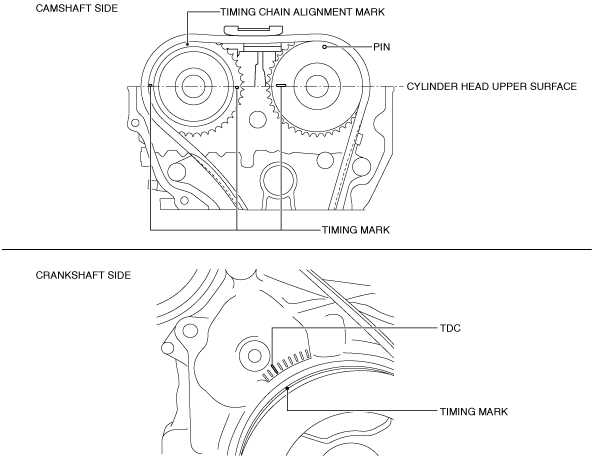
- (1) Rotate the crankshaft clockwise so that cylinder No.1 is positioned around before top dead center (TDC) as shown in the figure.
-
-
Note
-
• With cylinder No.1 positioned around before top dead center (TDC), there is no large movement (rotation) of the exhaust camshaft when the timing chain is removed. Therefore, installation of the electric variable valve timing actuator to the camshaft will be easier. (If there is a large movement of the exhaust camshaft, installation of the electric variable valve timing actuator to the camshaft must be performed while loosening the chain by rotating the exhaust camshaft.)
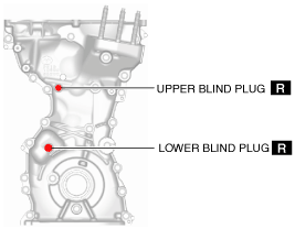
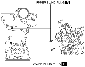
- (2) Remove the blind plugs (upper and lower) on the engine front cover service holes.
-
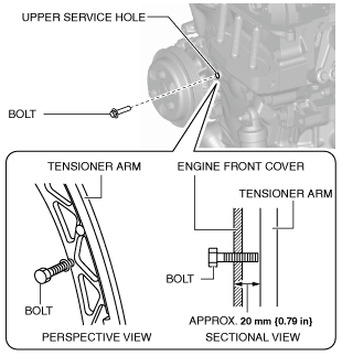
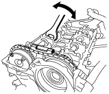
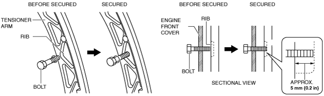
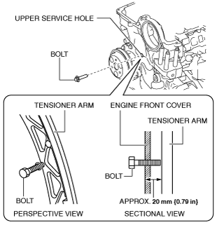
- (3) Insert an M6 bolt (35—60 mm {1.4—2.3 in} length with thread to the end) to the upper service hole and tighten it until it contacts the tensioner arm, then loosen it approx. 180 degrees (set the bolt so that it sits slightly in front of the tensioner arm).
-
-
Note
-
• The bolt contacts the tensioner arm when it is inserted approx. 20 mm {0.79 in}.
• The edge of the bolt in the upper service hole can be verified from the engine upper side (gap between engine front cover and engine).
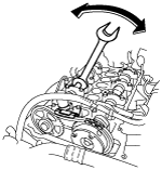
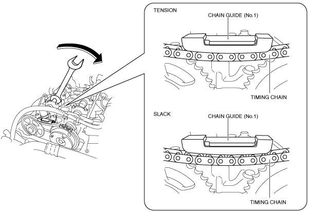
• Hold the exhaust camshaft using a wrench on the cast hexagon and move it back and forth a few times as shown in the figure. This will drain the oil from the chain tensioner and make the following servicing easier.
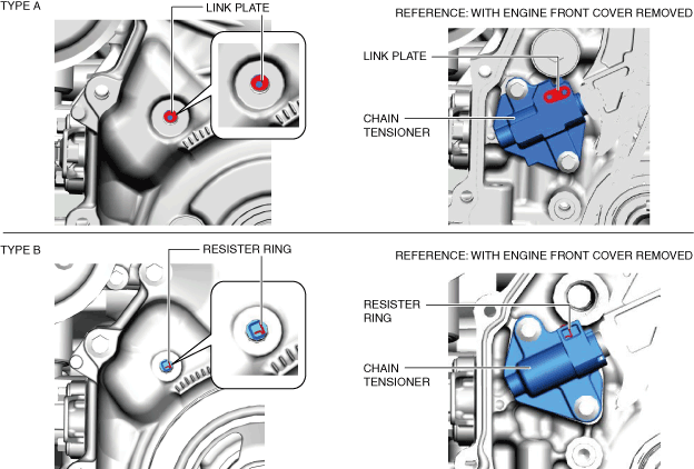
- (4) Verify the chain tensioner shape from the lower service hole and identify the chain tensioner type.
-
-
Note
-
• Verifying the chain tensioner type is necessary because the following procedures may differ according to the type of tensioner.
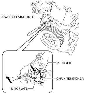
- (5) Insert a precision screwdriver into the lower service hole. (Chain tensioner (type A))
-
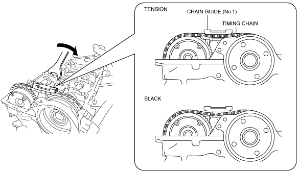
- (6) While moving the exhaust camshaft back and forth in the direction of the arrow using a wrench on the cast hexagon, press down the link plate of the timing chain tensioner using a precision screwdriver and release the plunger lock. (Chain tensioner (type A))
-
-
Note
-
• When moving the exhaust camshaft back and forth, the timing chain pushes the plunger in the chain tensioner making it easier to operate the link plate.
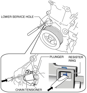
- (7) Insert a thin flathead screwdriver (precision screwdriver) into the lower service hole and press the chain tensioner resister ring. (Chain tensioner (type B))
-
-
Caution
-
• If excessive force is applied to the resister ring, it may cause the resister ring to deform. When pressing the resister ring, be careful not to apply excessive force.
-
Note
-
• The plunger lock is released by pressing the chain tensioner resister ring.
- (8) With the plunger lock released, rotate the exhaust camshaft clockwise until the timing chain loosens.
-
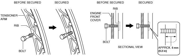
- (9) With the chain loosened, tighten the M6 bolt in the upper service hole so that the bolt is inserted approx. 5 mm {0.2 in} additionally to secure the tensioner arm.
-
-
Note
-
• By rotating the exhaust camshaft clockwise, the timing chain pushes the tensioner arm and the rib position deviates. The entire tensioner arm can be secured by hooking the bolt onto the deviated rib.
-
• If the bolt cannot be inserted approx. 5 mm {0.2 in}, the plunger lock of the chain tensioner may not release, or the chain may not loosen enough. Return the bolt to the original position and restart the procedure from Step (3).
- (10) After securing the tensioner arm, remove the chain guide (No.1).
-
Exhaust camshaft sprocket removal note
-
Caution
-
• Keep the timing chain pulled up during and after the work in which it has been set aside from the sprocket. If the chain falls down, it may disengage from the sprocket on the crankshaft side and deviate, leading to valve timing deviation.
• After servicing, always verify the valve timing.
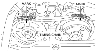
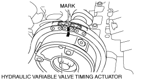
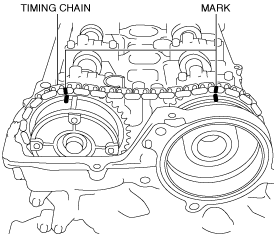
1. Mark the timing chain, hydraulic variable valve timing actuator, and exhaust camshaft sprocket so that they can be reassembled in the same condition as before removal.
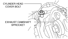
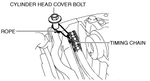
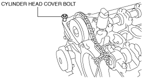
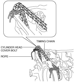
2. Temporarily install the cylinder head cover bolt to the position shown in the figure to use it for suspending the timing chain.
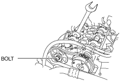
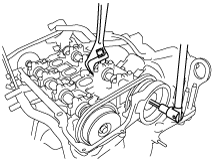
3. Hold the exhaust camshaft using a wrench on the cast hexagon, and loosen the exhaust camshaft sprocket installation bolt.
4. Remove the exhaust camshaft sprocket installation bolt.
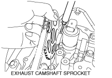
5. Using a screwdriver wrapped in a cloth, lightly press the exhaust camshaft sprocket to the front and separate the exhaust camshaft and the sprocket.
6. Remove the exhaust camshaft sprocket.
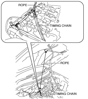
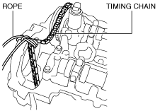
7. Pull up the timing chain and suspend it using a rope as shown in the figure.
Hydraulic variable valve timing actuator and intake camshaft component removal note
-
Caution
-
• Keep the timing chain pulled up during and after the work in which it has been set aside from the sprocket. If the chain falls down, it may disengage from the sprocket on the crankshaft side and deviate, leading to valve timing deviation.
• After servicing, always verify the valve timing.
1. Leave the timing chain which was suspended after exhaust camshaft sprocket removal, as it is.
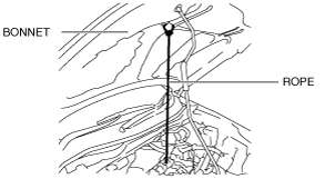
2. Suspend a string from the hood to use for suspending the timing chain.
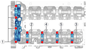
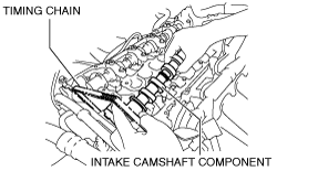
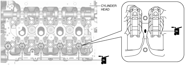
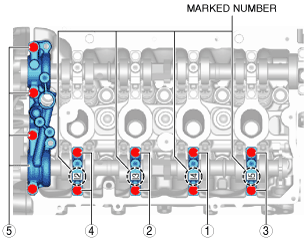
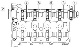
3. Loosen the intake-side camshaft cap bolts in two or three passes in the order shown in the figure, and remove the camshaft caps.
4. While setting the timing chain aside, remove the hydraulic variable valve timing actuator and the intake camshaft as a single unit.
5. Pull up the timing chain and suspend it using a rope as shown in the figure.
Hydraulic variable valve timing actuator removal note
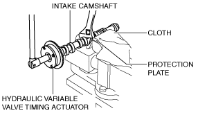
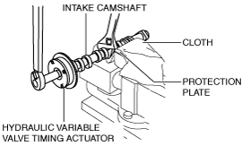
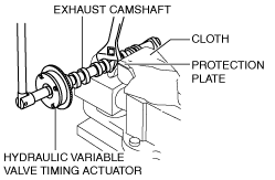
1. Lock the intake camshaft against rotation by holding the intake camshaft with a vise and securing the cast hexagon with a wrench.
2. Loosen the hydraulic variable valve timing actuator installation bolt and remove the actuator.
Hydraulic variable valve timing actuator installation note
1. When replacing the hydraulic variable valve timing actuator with a new one, mark the same positions as those marked before removal.
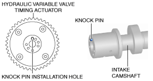
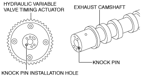
2. Align the knock pin on the end of the intake camshaft with the knock pin installation hole on the actuator side, and temporarily assemble the bolt.
3. Lock the intake camshaft against rotation by holding the intake camshaft with a vise and securing the cast hexagon with a wrench.
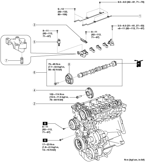
4. Tighten the hydraulic variable valve timing actuator installation bolt.
-
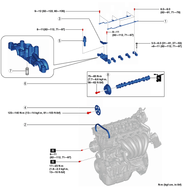
Tightening torque
-
75—85 N·m {7.7—8.6 kgf·m, 56—62 ft·lbf}
Hydraulic variable valve timing actuator and intake camshaft component installation note
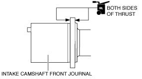
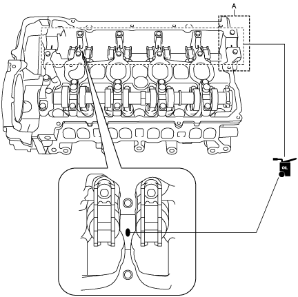
1. Apply SAE 90 gear oil or equivalent, or engine oil to the positions shown in the figure.
2. Apply SAE 90 gear oil or equivalent, or engine oil to the positions shown in the figure.
3. Remove the rope suspending the timing chain on the intake side.
4. While aligning the mark on the timing chain marked during removal with the one on the hydraulic variable valve timing actuator, mark the intake camshaft component on the cylinder head.
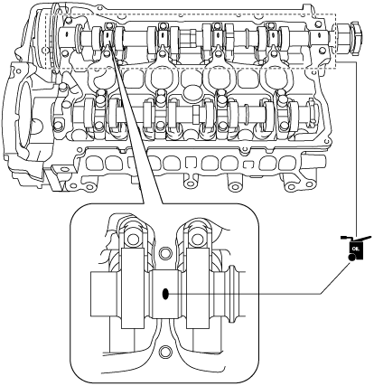
5. Apply SAE 90 gear oil or equivalent, or engine oil to the central area of each journal on the intake camshaft.
6. Install the intake-side camshaft caps in the order of the marked numbers, and temporarily tighten the camshaft cap installation bolts evenly in 2—3 rounds.
7. Tighten the camshaft cap installation bolts in two steps in the order shown in the figure.
-
Tightening torque
-
Step 1: 3.0—6.0 N·m {31—61 kgf·cm, 27—53 in·lbf}
Step 2: 8—11 N·m {82—112 kgf·cm, 71—97 in·lbf}
Exhaust camshaft sprocket installation note
1. When newly replacing the exhaust camshaft sprocket, mark the same positions as those marked during removal.
2. Remove the rope suspending the timing chain on the exhaust side.
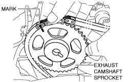
3. While aligning the mark on the timing chain marked during removal with the one on the exhaust camshaft sprocket, engage the chain with the sprocket.
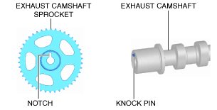
4. Align the knock pin on the end of the exhaust camshaft with the notch on the exhaust camshaft sprocket side, then assemble the sprocket.
-
Note
-
• Adjust the knock pin with the notch while adjusting the knock pin position by rotating the camshaft.
5. Tighten the exhaust camshaft sprocket installation bolt using the following procedure:
- (1) Temporarily tighten the exhaust camshaft sprocket installation bolt.
-
- (2) Hold the exhaust camshaft using a wrench on the cast hexagon, and tighten the exhaust camshaft sprocket installation bolt.
-
-
Tightening torque
-
123—140 N·m {13—14 kgf·m, 91—103 ft·lbf}
-
Note
-
• If there is no appropriate tool which can be used to tighten the camshaft sprocket installation bolt to the specified tightening torque, tighten the bolt using the method as shown in the figure. For the specified tightening torque calculation method if the tool is elongated, refer to the [SERVICE CAUTIONS] in the general information. (See
SERVICE CAUTIONS.)
Timing chain installation note
1. Install the chain guide (No.1).
2. Remove the bolt securing the tensioner arm and apply tension to the timing chain.
3. Rotate the crankshaft clockwise two turns and verify that the valve timing is correct.
-
Note
-
• The timing mark (camshaft side) is not completely parallel with the upper surface of the cylinder head.
-
4. Install the blind plugs (upper and lower) for the engine front cover service holes.
-
Tightening torque
-
Upper: 8—11 N·m {82—112 kgf·cm, 71—97 in·lbf}
Lower: 17—23 N·m {1.8—2.3 kgf·m, 13—16 ft·lbf}
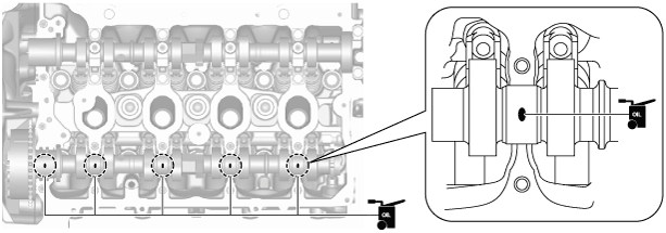
Oil shower pipe installation note
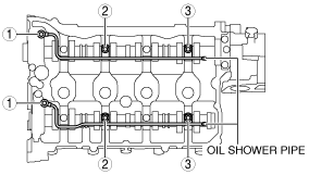
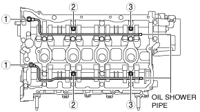
1. Install the oil shower pipe in the order shown in the figure.
Tightening torque
|
Installation position
|
Tightening torque
|
|
1
|
9—12 N·m {92—122 kgf·cm, 80—106 in·lbf}
|
|
2, 3
|
8.0—9.0 N·m {82—91 kgf·cm, 71—79 in·lbf}
|
SKYACTIV-G 1.5 (with 4-2-1 exhaust system)
-
Warning
-
• A hot engine can cause severe burns. Turn off the engine and wait until it is cool before servicing.
-
Caution
-
• Do not disassemble the electric variable valve timing actuator and hydraulic variable valve timing actuator because they are precision units.
• If the camshaft is rotated with the timing chain removed and the piston at the top dead center position, the valve may contact the piston and the engine could be damaged. When rotating the camshaft with the timing chain removed, rotate it after lowering the piston from the top dead center position.
• When rotating the camshaft using a wrench on the cast hexagon, the wrench may contact the rocker arm and damage the rocker arm. To prevent damage to the rocker arm when holding the camshaft on the cast hexagon, use a wrench on the rear side of the engine as shown in the figure to secure a clearance between the cam.
-
Note
-
• Width at the cast hexagon of the camshaft is
22—24 mm {0.87—0.94 in}.
1. Disconnect the negative battery cable. (See NEGATIVE BATTERY CABLE DISCONNECTION/CONNECTION.)
2. Remove the plug hole plate. (See PLUG HOLE PLATE REMOVAL/INSTALLATION [SKYACTIV-G 1.3, SKYACTIV-G 1.5].)
3. Remove the ignition coil/ion sensors. (See IGNITION COIL/ION SENSOR REMOVAL/INSTALLATION [SKYACTIV-G 1.3, SKYACTIV-G 1.5].)
4. Remove the cylinder head cover. (See TIMING CHAIN REMOVAL/INSTALLATION [SKYACTIV-G 1.3, SKYACTIV-G 1.5].)
5. Remove the electric variable valve timing motor/driver. (See ELECTRIC VARIABLE VALVE TIMING MOTOR/DRIVER REMOVAL/INSTALLATION [SKYACTIV-G 1.3, SKYACTIV-G 1.5].)
6. Remove the vacuum pump. (Only when hydraulic variable valve timing actuator is removed.) (See VACUUM PUMP REMOVAL/INSTALLATION [SKYACTIV-G 1.3, SKYACTIV-G 1.5].)
7. Remove the high pressure fuel pump and rear housing. (Only when hydraulic variable valve timing actuator is removed.) (See HIGH PRESSURE FUEL PUMP REMOVAL/INSTALLATION [SKYACTIV-G 1.3, SKYACTIV-G 1.5].)
8. Remove in the order indicated in the table.
9. Install in the reverse order of removal.
10. Start the engine and inspect the following:
-
|
1
|
Oil shower pipe
|
|
2
|
Timing chain
|
|
3
|
Chain guide (No.1)
|
|
4
|
Electric variable valve timing actuator
|
|
5
|
OCV
|
|
6
|
Hydraulic variable valve timing actuator and exhaust camshaft component
|
|
7
|
OCV oil filter
|
|
8
|
Hydraulic variable valve timing actuator
|
Timing chain removal note
1. Release the tension on the timing chain using the following procedure:
-
Note
-
• Release the tension on the timing chain by securing the timing chain tensioner arm through the service hole on the engine front cover.
- (1) Rotate the crankshaft clockwise so that cylinder No.1 is positioned around before top dead center (TDC) as shown in the figure.
-
-
Note
-
• With cylinder No.1 positioned around before top dead center (TDC), there is no large movement (rotation) of the exhaust camshaft when the timing chain is removed. Therefore, installation of the electric variable valve timing actuator to the camshaft will be easier. (If there is a large movement of the exhaust camshaft, installation of the electric variable valve timing actuator to the camshaft must be performed while loosening the chain by rotating the exhaust camshaft.)
- (2) Remove the blind plugs (upper and lower) on the engine front cover service holes.
-
- (3) Insert an M6 bolt (35—60 mm {1.4—2.3 in} length with thread to the end) to the upper service hole and tighten it until it contacts the tensioner arm, then loosen it approx. 180 degrees (set the bolt so that it sits slightly in front of the tensioner arm).
-
-
Note
-
• The bolt contacts the tensioner arm when it is inserted approx. 20 mm {0.79 in}.
• Hold the exhaust camshaft using a wrench on the cast hexagon and move it back and forth a few times as shown in the figure. This will drain the oil from the chain tensioner and make the following servicing easier.
- (4) Verify the chain tensioner shape from the lower service hole and identify the chain tensioner type.
-
-
Note
-
• Verifying the chain tensioner type is necessary because the following procedures may differ according to the type of tensioner.
- (5) Insert a precision screwdriver into the lower service hole. (Chain tensioner (type A))
-
- (6) While moving the exhaust camshaft back and forth in the direction of the arrow using a wrench on the cast hexagon, press down the link plate of the timing chain tensioner using a precision screwdriver and release the plunger lock. (Chain tensioner (type A))
-
-
Note
-
• When moving the exhaust camshaft back and forth, the timing chain pushes the plunger in the chain tensioner making it easier to operate the link plate.
- (7) Insert a thin flathead screwdriver (precision screwdriver) into the lower service hole and press the chain tensioner resister ring. (Chain tensioner (type B))
-
-
Caution
-
• If excessive force is applied to the resister ring, it may cause the resister ring to deform. When pressing the resister ring, be careful not to apply excessive force.
-
Note
-
• The plunger lock is released by pressing the chain tensioner resister ring.
- (8) With the plunger lock released, rotate the exhaust camshaft clockwise until the timing chain loosens.
-
- (9) With the chain loosened, tighten the M6 bolt in the upper service hole so that the bolt is inserted approx. 5 mm {0.2 in} additionally to secure the tensioner arm.
-
-
Note
-
• By rotating the exhaust camshaft clockwise, the timing chain pushes the tensioner arm and the rib position deviates. The entire tensioner arm can be secured by hooking the bolt onto the deviated rib.
-
• If the bolt cannot be inserted approx. 5 mm {0.2 in}, the plunger lock of the chain tensioner may not release, or the chain may not loosen enough. Return the bolt to the original position and restart the procedure from Step (3).
- (10) After securing the tensioner arm, remove the chain guide (No.1).
-
Electric variable valve timing actuator removal note
-
Caution
-
• Keep the timing chain pulled up during and after the work in which it has been set aside from the sprocket. If the chain falls down, it may disengage from the sprocket on the crankshaft side and deviate, leading to valve timing deviation.
• After servicing, always verify the valve timing.
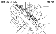
1. Mark the timing chain and each actuator so that they can be reassembled in the same condition as before removal.
2. Hold the intake camshaft using a wrench on the cast hexagon and remove the electric variable valve timing actuator installation bolt.
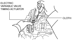
3. Using a screwdriver wrapped in a clean cloth, lightly press the electric variable valve timing actuator to the front and separate the intake camshaft and the actuator.
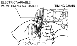
4. Remove the timing chain from the exhaust and intake camshaft sprockets and set is aside, and remove the electric variable valve timing actuator.
5. Return the timing chain to the exhaust camshaft sprocket, and pull the timing chain up and suspend it using a rope as shown in the figure.
Hydraulic variable valve timing actuator and exhaust camshaft component removal note
-
Caution
-
• Keep the timing chain pulled up during and after the work in which it has been set aside from the sprocket. If the chain falls down, it may disengage from the sprocket on the crankshaft side and deviate, leading to valve timing deviation.
• After servicing, always verify the valve timing.
1. Leave the timing chain as it is, which was suspended after electric variable valve timing actuator removal.
2. Temporarily install the cylinder head cover bolt to the position shown in the figure to use it for suspending the timing chain.
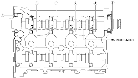
3. Loosen the exhaust-side camshaft cap bolts in two or three passes in the order shown in the figure, and remove the camshaft caps.
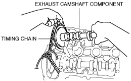
4. While setting the timing chain aside, remove the hydraulic variable valve timing actuator and the exhaust camshaft as a single unit.
5. Pull up the timing chain and suspend it using a rope as shown in the figure.
Hydraulic variable valve timing actuator removal note
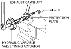
1. Lock the exhaust camshaft against rotation by holding the exhaust camshaft with a vise and securing the cast hexagon with a wrench.
2. Loosen the hydraulic variable valve timing actuator installation bolt and remove the actuator.
Hydraulic variable valve timing actuator installation note
1. When replacing the hydraulic variable valve timing actuator, place a mark at the same position as the one placed before removal.
2. Align the knock pin on the end of the exhaust camshaft with the knock pin installation hole on the actuator side, and temporarily assemble the bolt.
3. Lock the exhaust camshaft against rotation by holding the exhaust camshaft with a vise and securing the cast hexagon with a wrench.
4. Tighten the hydraulic variable valve timing actuator installation bolt.
-
Tightening torque
-
75—85 N·m {7.7—8.6 kgf·m, 56—62 ft·lbf}
Hydraulic variable valve timing actuator and exhaust camshaft component installation note
1. Apply SAE 90 gear oil or equivalent, or engine oil to the positions shown in the figure.
-
Caution
-
• Apply 0.05 ml {0.05 cc, 0.003 in3} or less of oil to area A in the figure.
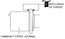
2. As shown in the figure, apply gear oil (SAE 90 or equivalent) or engine oil to the exhaust camshaft.
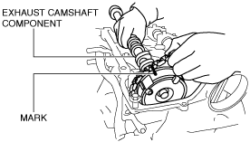
3. Remove the rope suspending the timing chain on the exhaust side.
4. While aligning the mark on the timing chain placed during removal with the one on the hydraulic variable valve timing actuator, place the exhaust camshaft component on the cylinder head.
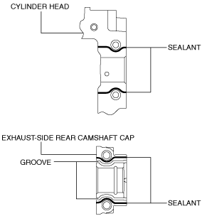
5. Apply SAE 90 gear oil or equivalent, or engine oil to the central area of each journal on the exhaust camshaft.
6. Apply sealant (Loctite #962T or equivalent) to the rear camshaft cap installation area on the exhaust side or the rear camshaft caps on the exhaust side of the cylinder head.
-
Note
-
• To prevent engine oil leakage, apply sealant to the rear camshaft cap installation area on the exhaust side or the rear camshaft caps on the exhaust side of the cylinder head, and seal the journal.
-
Caution
-
• Do not spill sealant on the journal.
-
Sealant bead width
-
0.5—1.5 mm {0.02—0.05 in}
7. Install the camshaft caps in the marked number order, and temporarily tighten the camshaft cap installation bolts in two or three passes evenly.
8. Tighten the camshaft cap installation bolts in two steps in the order shown in the figure.
-
Tightening torque
-
Step 1: 3.0—6.0 N·m {31—61 kgf·cm, 27—53 in·lbf}
Step 2: 8—11 N·m {82—112 kgf·cm, 71—97 in·lbf}
Electric variable valve timing actuator installation note
1. When replacing the electric variable valve timing actuator with a new one, place a mark at the same position as the one placed before removal.
2. Remove the rope suspending the timing chain on the intake side.
3. Remove the timing chain from the exhaust and intake camshaft sprockets and set it aside to the rear, then insert the electric variable valve timing actuator between the engine front cover and the cylinder head.
4. Return the timing chain to the exhaust camshaft sprocket.
5. While aligning the mark on the timing chain placed during removal with the one on the electric variable valve timing actuator, engage the chain with the sprocket.
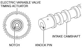
6. Align the knock pin on the end of the intake camshaft with the notch on the actuator side, then assemble the actuator.
-
Note
-
• Adjust the knock pin with the notch while adjusting the knock pin position by rotating the camshaft.
7. Hold the intake camshaft using a wrench on the cast hexagon, and tighten the electric variable valve timing actuator installation bolt.
-
Tightening torque
-
102—114 N·m {10.5—11.6 kgf·m, 76—84 ft·lbf}
Timing chain installation note
1. Install the chain guide (No.1).
2. Remove the bolt securing the tensioner arm and apply tension to the timing chain.
3. Rotate the crankshaft clockwise two turns and verify that the valve timing is correct.
-
Note
-
• The timing mark (camshaft side) is not completely parallel with the upper surface of the cylinder head.
-
4. Install the blind plugs (upper and lower) for the engine front cover service holes.
-
Tightening torque
-
Upper: 8—11 N·m {82—112 kgf·cm, 71—97 in·lbf}
Lower: 17—23 N·m {1.8—2.3 kgf·m, 13—16 ft·lbf}
Oil shower pipe installation note
1. Install the oil shower pipe in the order shown in the figure.
Tightening torque
|
Installation position
|
Tightening torque
|
|
1
|
9—12 N·m {92—122 kgf·cm, 80—106 in·lbf}
|
|
2, 3
|
8.0—9.0 N·m {82—91 kgf·cm, 71—79 in·lbf}
|