COMPRESSION INSPECTION [SKYACTIV-G 1.3, SKYACTIV-G 1.5]
id0110q3800300
-
Warning
-
• Hot engines and oil can cause severe burns. Be careful not to burn yourself during removal/installation of each component.
• Fuel vapor is hazardous. It can very easily ignite, causing serious injury and damage. Always keep sparks and flames away from fuel.
-
Note
-
• For the general (R.H.D.) specification, engine compression ratios of 13 and 14 are included and the specified value of each compression pressure differs. The compression ratio can be identified by the part number of the piston set, therefore, verify the part number of the piston set using the following procedure:
-
1. Input the vehicle identification number (VIN) into the "Mazda Electronic Parts Catalog".
2. Record the part number of the piston set.
-
― P5Y1-11SA0 (Compression ratio of 14)
― P5Y2-11SA0 (Compression ratio of 13)
1. Verify that the battery is fully charged. (See BATTERY INSPECTION.)
-
2. Connect the M-MDS to the DLC-2.
3. Warm up the engine to the normal operating temperature.
4. Display the following PIDs using the M-MDS data monitor function. (See PCM INSPECTION [SKYACTIV-G 1.3, SKYACTIV-G 1.5].)
-
• RPM (engine speed)
5. Perform “Fuel Line Safety Procedures”. (See BEFORE SERVICE PRECAUTION [SKYACTIV-G 1.3, SKYACTIV-G 1.5].)
6. Remove the following parts:
- (1) Plug hole plate (See PLUG HOLE PLATE REMOVAL/INSTALLATION [SKYACTIV-G 1.3, SKYACTIV-G 1.5].)
- (2) Fuel injector relay
- (3) Ignition coils (SKYACTIV-G 1.3, SKYACTIV-G 1.5 (with 4-1 exhaust system)) (See IGNITION COIL/ION SENSOR REMOVAL/INSTALLATION [SKYACTIV-G 1.3, SKYACTIV-G 1.5].)
- (4) Ignition coil/ion sensors (SKYACTIV-G 1.5 (with 4-2-1 exhaust system)) (See IGNITION COIL/ION SENSOR REMOVAL/INSTALLATION [SKYACTIV-G 1.3, SKYACTIV-G 1.5].)
- (5) Spark plugs (See SPARK PLUG REMOVAL/INSTALLATION [SKYACTIV-G 1.3, SKYACTIV-G 1.5].)
7. Measure the compression pressure using the following procedure.
- (1) Install the compression gauge to the spark plug hole.
- (2) Fully depress the accelerator pedal.
-
-
Note
-
• The cranking method is as follows.
MTX
-
― When the ignition switch is pressed with the clutch pedal depressed, cranking starts.
― When your foot is removed from the clutch pedal during cranking, cranking stops.
― When the ignition switch is pressed during cranking, cranking stops.
ATX
-
― When the ignition switch is pressed with the brake pedal depressed, cranking starts.
― When the ignition switch is pressed during cranking, cranking stops.
- (3) Crank the engine and measure the following values simultaneously.
-
-
• Compression pressure
• Engine speed
-
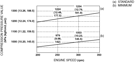
Compression pressure [SKYACTIV-G 1.3]
-
Standard: Refer to the graph.
Minimum: Refer to the graph.
Maximum difference between cylinders: 208 kPa {2.12 kgf/cm2, 30.2 psi} [250 rpm]
-
Compression pressure [SKYACTIV-G 1.5 (with 4-1 exhaust system)]
-
Standard: Refer to the graph.
Minimum: Refer to the graph.
Maximum difference between cylinders: 211 kPa {2.15 kgf/cm2, 30.6 psi} [250 rpm]
-
Compression pressure [SKYACTIV-G 1.5 (with 4-2-1 exhaust system)] (Compression ratio of 13)
-
Standard: Refer to the graph.
Minimum: Refer to the graph.
Maximum difference between cylinders: 105 kPa {1.07 kgf/cm2, 15.2 psi} [250 rpm]
-
Compression pressure [SKYACTIV-G 1.5 (with 4-2-1 exhaust system)] (Compression ratio of 14)
-
Standard: Refer to the graph.
Minimum: Refer to the graph.
Maximum difference between cylinders: 146 kPa {1.49 kgf/cm2, 21.2 psi} [250 rpm]
- (4) Perform Steps (1) to (3) for all cylinders.
- (5) If the measured value is the threshold or less, or if there is a cylinder which exceeds the specified maximum difference between cylinders, add a small amount of engine oil through the spark plug hole and perform Steps (1) to (3).
-
-
• If the pressure increases by adding the engine oil, the piston ring or the cylinder surface is worn, or they are damaged. Perform overhaul servicing.
-
• If the pressure does not increase, valve seizure, valve attachment malfunction, or pressure leakage from the cylinder head gasket might be occurring. Perform overhaul servicing.
- (6) If the measured value is high, it is possible that there is an error in the electric variable valve timing system. (SKYACTIV-G 1.5 (with 4-2-1 exhaust system))
8. Remove the compression gauge.
9. Install the following parts:
- (1) Spark plugs (See SPARK PLUG REMOVAL/INSTALLATION [SKYACTIV-G 1.3, SKYACTIV-G 1.5].)
- (2) Ignition coil/ion sensors (SKYACTIV-G 1.5 (with 4-2-1 exhaust system)) (See IGNITION COIL/ION SENSOR REMOVAL/INSTALLATION [SKYACTIV-G 1.3, SKYACTIV-G 1.5].)
- (3) Ignition coils (SKYACTIV-G 1.3, SKYACTIV-G 1.5 (with 4-1 exhaust system)) (See IGNITION COIL/ION SENSOR REMOVAL/INSTALLATION [SKYACTIV-G 1.3, SKYACTIV-G 1.5].)
- (4) Fuel injector relay
- (5) Plug hole plate (See PLUG HOLE PLATE REMOVAL/INSTALLATION [SKYACTIV-G 1.3, SKYACTIV-G 1.5].)
 am2zzw00012832Standard: Refer to the graph.Minimum: Refer to the graph.Maximum difference between cylinders: 208 kPa {2.12 kgf/cm2, 30.2 psi} [250 rpm]
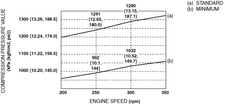 am2zzw00012833Standard: Refer to the graph.Minimum: Refer to the graph.Maximum difference between cylinders: 211 kPa {2.15 kgf/cm2, 30.6 psi} [250 rpm]
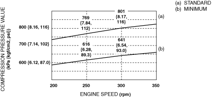 am2zzw00012834Standard: Refer to the graph.Minimum: Refer to the graph.Maximum difference between cylinders: 105 kPa {1.07 kgf/cm2, 15.2 psi} [250 rpm]
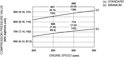 am2zzw00012835Standard: Refer to the graph.Minimum: Refer to the graph.Maximum difference between cylinders: 146 kPa {1.49 kgf/cm2, 21.2 psi} [250 rpm]