|
am2zzw00012307
OIL CONTROL VALVE (OCV) INSPECTION [SKYACTIV-G 1.3, SKYACTIV-G 1.5]
id0110q3801400
SKYACTIV-G 1.3, SKYACTIV-G 1.5 (With 4-1 Exhaust System)
Coil Resistance Inspection
1. Disconnect the negative battery cable. (See NEGATIVE BATTERY CABLE DISCONNECTION/CONNECTION.)
2. Remove the plug hole plate. (See PLUG HOLE PLATE REMOVAL/INSTALLATION [SKYACTIV-G 1.3, SKYACTIV-G 1.5].)
3. Disconnect the OCV connector. (See OIL CONTROL VALVE (OCV) REMOVAL/INSTALLATION [SKYACTIV-G 1.3, SKYACTIV-G 1.5].)
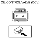
4. Measure the resistance between terminals A and B using an ohmmeter.
am2zzw00012307
|
5. Install in the reverse order of removal.
Spool Valve Operation Inspection
1. Disconnect the negative battery cable. (See NEGATIVE BATTERY CABLE DISCONNECTION/CONNECTION.)
2. Remove the plug hole plate. (See PLUG HOLE PLATE REMOVAL/INSTALLATION [SKYACTIV-G 1.3, SKYACTIV-G 1.5].)
3. Remove the ignition coil. (See IGNITION COIL/ION SENSOR REMOVAL/INSTALLATION [SKYACTIV-G 1.3, SKYACTIV-G 1.5].)
4. Remove the cylinder head cover. (See TIMING CHAIN REMOVAL/INSTALLATION [SKYACTIV-G 1.3, SKYACTIV-G 1.5].)
5. Remove the OCV. (See OIL CONTROL VALVE (OCV) REMOVAL/INSTALLATION [SKYACTIV-G 1.3, SKYACTIV-G 1.5].)
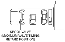
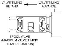
6. Verify that the spool valve in the OCV is in the maximum valve timing retard position as indicated in the figure.
am2zzw00012308
|
7. Verify that the battery is fully charged. (See BATTERY INSPECTION.)
am2zzw00012307
|
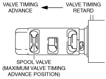
8. Apply battery positive voltage between the OCV terminals and verify that the spool valve operates and moves to the maximum valve timing advance position.
am2zzw00012309
|
9. Stop applying battery positive voltage and verify that the spool valve returns to the maximum valve timing retard position.
10. Install the OCV. (See OIL CONTROL VALVE (OCV) REMOVAL/INSTALLATION [SKYACTIV-G 1.3, SKYACTIV-G 1.5].)
SKYACTIV-G 1.5 (With 4-2-1 Exhaust System)
Coil Resistance Inspection
1. Disconnect the negative battery cable. (See NEGATIVE BATTERY CABLE DISCONNECTION/CONNECTION.)
2. Remove the plug hole plate. (See PLUG HOLE PLATE REMOVAL/INSTALLATION [SKYACTIV-G 1.3, SKYACTIV-G 1.5].)
3. Disconnect the OCV connector. (See OIL CONTROL VALVE (OCV) REMOVAL/INSTALLATION [SKYACTIV-G 1.3, SKYACTIV-G 1.5].)
4. Measure the resistance between terminals A and B using an ohmmeter.
am2zzw00012310
|
5. Install in the reverse order of removal.
Spool Valve Operation Inspection
1. Disconnect the negative battery cable. (See NEGATIVE BATTERY CABLE DISCONNECTION/CONNECTION.)
2. Remove the plug hole plate. (See PLUG HOLE PLATE REMOVAL/INSTALLATION [SKYACTIV-G 1.3, SKYACTIV-G 1.5].)
3. Remove the ignition coil/ion sensors. (See IGNITION COIL/ION SENSOR REMOVAL/INSTALLATION [SKYACTIV-G 1.3, SKYACTIV-G 1.5].)
4. Remove the cylinder head cover. (See TIMING CHAIN REMOVAL/INSTALLATION [SKYACTIV-G 1.3, SKYACTIV-G 1.5].)
5. Remove the OCV. (See OIL CONTROL VALVE (OCV) REMOVAL/INSTALLATION [SKYACTIV-G 1.3, SKYACTIV-G 1.5].)
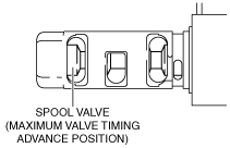
6. Verify that the spool valve in the OCV is in the maximum valve timing advance position as indicated in the figure.
am2zzw00012311
|
7. Verify that the battery is fully charged. (See BATTERY INSPECTION.)
am2zzw00012310
|
8. Apply battery positive voltage between the OCV terminals and verify that the spool valve operates and moves to the maximum valve timing retard position.
am2zzw00012312
|
9. Stop applying battery positive voltage and verify that the spool valve returns to the maximum valve timing advance position.
10. Install the OCV. (See OIL CONTROL VALVE (OCV) REMOVAL/INSTALLATION [SKYACTIV-G 1.3, SKYACTIV-G 1.5].)