 |
am2zzw00011951
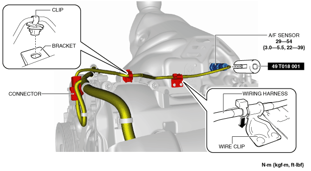
AIR FUEL RATIO (A/F) SENSOR REMOVAL/INSTALLATION [SKYACTIV-G 1.3, SKYACTIV-G 1.5]
id0140q1899700
SKYACTIV-G 1.3, SKYACTIV-G 1.5 (With 4-1 Exhaust System)
1. Disconnect the negative battery cable. (See NEGATIVE BATTERY CABLE DISCONNECTION/CONNECTION.)
2. Disconnect the A/F sensor connector.
am2zzw00011951
|
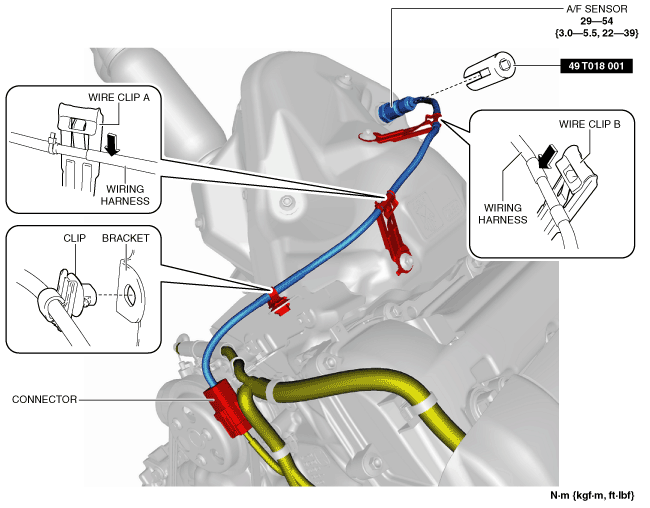
3. Remove the clip from the bracket.
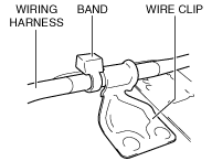
4. Push out the wiring harness in the direction of the arrow shown in the figure, and remove the wiring harness from the wire clip. (See Assembly of wiring harness to wire clip note.)
5. Remove the A/F sensor using the SST.
6. Install in the reverse order of removal.
Assembly of wiring harness to wire clip note
am2zzw00011952
|
SKYACTIV-G 1.5 (With 4-2-1 Exhaust System)
1. Disconnect the negative battery cable. (See NEGATIVE BATTERY CABLE DISCONNECTION/CONNECTION.)
2. Disconnect the A/F sensor connector.
am2zzw00011953
|
3. Remove the clip from the bracket.
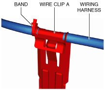
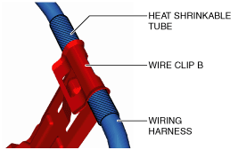
4. Push out the wiring harness in the direction of the arrows shown in the figure, and remove the wiring harness from the wire clip A and B. (See Assembly of wiring harness to wire clip note.)
5. Remove the A/F sensor using the SST.
6. Install in the reverse order of removal.
Assembly of wiring harness to wire clip note
adejjw00008901
|
adejjw00008902
|