 |
am2zzw00008132
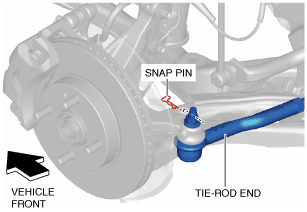
TIE-ROD END REPLACEMENT
id061300801200
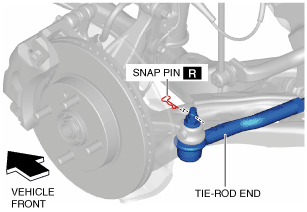
1. Remove the snap pin from the tie-rod end.
am2zzw00008132
|
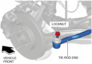
2. Loosen the locknut of the tie-rod end.
am2zzw00008133
|
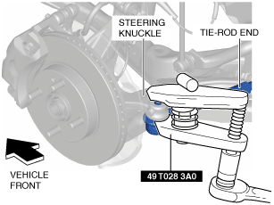
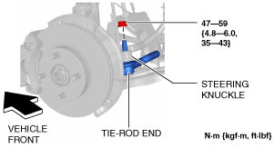
3. Using the SST, disconnect the steering knuckle and tie-rod end.
am2zzw00008134
|
4. Remove the locknut from the tie-rod end.
am2zzw00008135
|
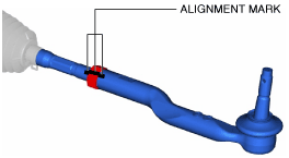
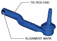
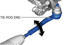
5. Place alignment marks as shown in the figure for proper installation.
am2zzw00008136
|
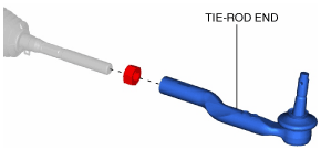
6. Remove the tie-rod end.
am2zzw00008137
|
7. Place alignment marks on the new tie-rod end in the same positions as the removed tie-rod end.
am2zzw00008138
|
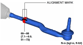
8. Align the marks that were made before removing the tie-rod end, and assemble the tie-rod end to the tie rod.
am2zzw00008139
|
am2zzw00008726
|
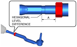
9. Verify that dimension A shown in the figure is within the specification.
am2zzw00008727
|
10. Install the tie-rod end to the steering knuckle.
am2zzw00008142
|
11. Install a new snap pin to the tie-rod end.
am2zzw00008143
|
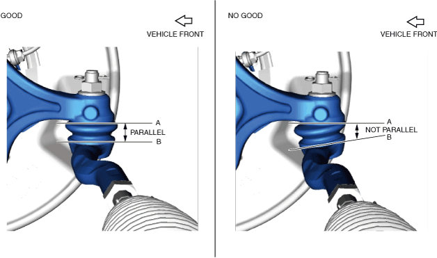
12. Verify that A and B shown in the figure are parallel while the vehicle is on the ground.
am2zzw00015383
|
am2zzw00015169
|
13. After installation, inspect the front wheel alignment and adjust it if necessary. (See FRONT WHEEL ALIGNMENT.)