|
1
|
INSPECT LF CONTROL UNIT CONNECTOR CONDITION
• Switch the ignition off.
• Disconnect the negative battery cable.
• Disconnect the LF control unit connector.
• Inspect the connector engagement and connection condition and inspect the terminals for damage, deformation, corrosion, or disconnection.
• Is the connector normal?
|
Yes
|
Go to the next step.
|
|
2
|
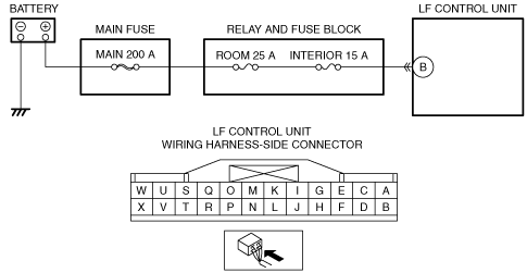
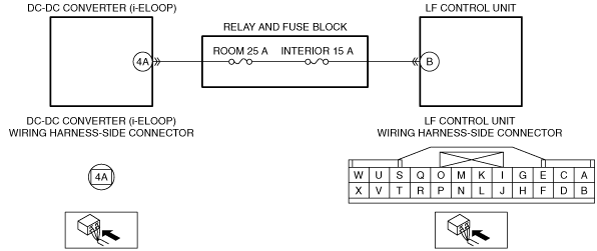
VERIFY LF CONTROL UNIT POWER SUPPLY VOLTAGE
• Always reconnect all disconnected connectors.
• Connect the negative battery cable.
• Measure the voltage at the LF control unit terminal B (wiring harness-side).
• Is the voltage 5 V or more or less than 8.5 V?
|
Yes
|
Refer to the wiring diagram and verify whether or not there is a common connector between battery positive terminal and LF control unit terminal B.
If there is a common connector:
• Determine the malfunctioning part by inspecting the common connector and the terminal for corrosion, damage, or pin disconnection, and the common wiring harness for a malfunction.
• Repair or replace the malfunctioning part.
If there is no common connector:
• Inspect the wiring harness between battery positive terminal and LF control unit terminal B.
-
― If there is any malfunction:
-
• Repair or replace the wiring harness.
― If there is no malfunction:
-
• Replace the LF control unit.
Go to Step 4.
|
|
4
|
VERIFY THAT REPAIRS HAVE BEEN COMPLETED
• Always reconnect all disconnected connectors.
• Connect the negative battery cable.
• Clear the DTC for the advanced keyless entry system using the M-MDS.
• Switch the ignition ON (engine off) and wait for 5 s or more.
• Retrieve the advanced keyless entry system DTCs using the M-MDS.
• Is the same DTC displayed?
|
Yes
|
Repeat the inspection from Step 1.
• If the malfunction recurs, replace the start stop unit.
Go to the next step.
|