 |
am2zzw00008337
INTRUDER SENSOR INSPECTION
id091400517300
1. Remove the front map light. (See FRONT MAP LIGHT REMOVAL/INSTALLATION.)
2. Remove the intruder sensor with the connector connected. (See INTRUDER SENSOR REMOVAL/INSTALLATION.)
3. Verify that the voltages of each of the terminals are as indicated in the terminal voltage table (reference).
Terminal Voltage Table (Reference)
am2zzw00008337
|
|
Terminal |
Signal name |
Connected to |
Measurement condition |
Voltage (V) |
Inspection item (s) |
|---|---|---|---|---|---|
|
B
|
Ground
|
BCM
|
Under any condition
|
1.0 or less
|
BCM
|
|
C
|
DATA
|
BCM
|
Because this terminal is for communication, determination using terminal voltage inspection is not possible.
|
||
|
D
|
Power supply
|
BCM
|
Under any condition
|
B+
|
BCM
|
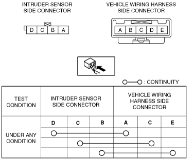
Continuity Inspection Of Short Wiring Harness Connector
1. Verify that the continuity is as indicated in the table.
am2zzw00008338
|