 |
am6zzw00009104
RELAY INSPECTION
id092100800300
Relay Type
|
Connector type |
Part name |
|---|---|
|
Type A
|
• IG1 RELAY
• A/C RELAY
• FRONT FOG LIGHT RELAY
• HEADLIGHT CLEANER RELAY
• THEFT-DETERRENT RELAY
• ELECTRIC AT OIL PUMP RELAY
• IGNITION RELAY (ACC_STAB)
• HORN RELAY
• STARTER RELAY
• ELECTRIC VARIABLE VALVE TIMING RELAY
• ACC RELAY
• REAR WINDOW DEFROSTER RELAY
• IGNITION RELAY (IG1_STAB)
• FUEL PUMP RELAY*1
• BLOW-BY HEATER RELAY*2
• FUEL INJECTOR RELAY*1
• CHECK CONNECTOR*2
• MAIN RELAY
• COOLING FAN RELAY NO.1*1
• COOLING FAN RELAY NO.2*1
|
|
Type B
|
• BRAKE LIGHT RELAY
• WIPER INT RELAY
• WIPER HI RELAY
|
|
Type C
|
• BLOWER RELAY
• COOLING FAN RELAY
|
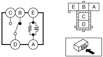
Type A
1. Remove the relay. (See RELAY LOCATION.)
2. Verify the continuity between relay terminals C and D.
am6zzw00009104
|
3. Verify the continuity between relay terminals E and A.
4. Apply battery voltage to relay terminal E, and connect terminal A to ground.
5. Verify the continuity between relay terminals C and D.
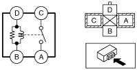
Type B
1. Remove the relay. (See RELAY LOCATION.)
2. Verify the continuity between relay terminals C and D.
ac5wzw00000084
|
3. Verify the continuity between the relay terminals E and A.
4. Verify the continuity between the relay terminals B and D.
5. Apply battery voltage to relay terminal E, and connect terminal A to ground.
6. Verify the continuity between relay terminals C and D.
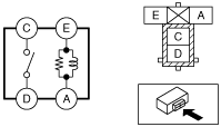
Type C
1. Remove the relay. (See RELAY LOCATION.)
2. Verify the continuity between the relay terminals C and A.
ac5wzw00000085
|
3. Verify the continuity between the relay terminals D and B.
4. Apply battery voltage to relay terminal D, and connect terminal B to ground.
5. Verify the continuity between relay terminals C and A.