FUEL GAUGE SENDER UNIT REMOVAL/INSTALLATION
id092200012000
-
Warning
-
• Always keep sparks and flames away from fuel when servicing the fuel system. Fuel can be easily ignited which could cause serious injury or death, and damage to equipment.
• Fuel line spills and leakage from the pressurized fuel system are dangerous. Fuel can ignite and cause serious injury or death and damage. Fuel can also irritate skin and eyes. To prevent this, always complete the Fuel Line Safety Procedure, while referring to the BEFORE SERVICE PRECAUTION.
• A person charged with static electricity could cause a fire or explosion, resulting in death or serious injury. Before draining fuel, make sure to discharge static electricity by touching a vehicle.
-
Caution
-
• If the fuel gauge level indicates 3/4 or more, the fuel surface is higher than the fuel pump unit and fuel gauge sender unit installation surface. If servicing is performed under this condition, fuel leakage could result. Always drain the fuel before performing the operation and keep the fuel in the fuel tank at less than half.
• Disconnecting/connecting the quick release connector without cleaning it may cause damage to the fuel pipe and quick release connector. Always clean the quick release connector joint area before disconnecting/connecting using a cloth or soft brush, and make sure that it is free of foreign material.
SKYACTIV-G 1.3
-
Note
-
SKYACTIV-D 1.5
1. Perform the "Fuel Line Safety Procedure" referring to the "BEFORE REPAIR PROCEDURE". (See BEFORE SERVICE PRECAUTION [SKYACTIV-D 1.5].)
2. If the fuel gauge level indicates 3/4 or more, refer to the "FUEL DRAINING PROCEDURE" and drain the fuel. (See FUEL DRAINING PROCEDURE [SKYACTIV-D 1.5].)
3. Disconnect the negative battery cable. (See NEGATIVE BATTERY CABLE DISCONNECTION/CONNECTION.)
4. Remove the rear seat cushion. (See REAR SEAT CUSHION REMOVAL/INSTALLATION.)
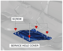
5. Remove the screws.
6. Remove the service hole cover.
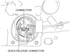
7. Disconnect the connector.
8. Disconnect the quick release connector. (See QUICK RELEASE CONNECTOR REMOVAL/INSTALLATION [SKYACTIV-D 1.5].)
-
Caution
-
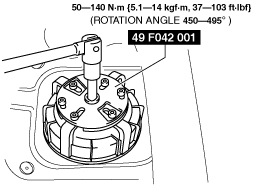
• The fuel gauge sender unit cap could be damaged if the SST (wrench) is used with any gap between the cap and the SST (wrench). Securely attach the SST (wrench) so that there is no gap between the SST (wrench) tabs and the side of the cap.
9. Remove the fuel gauge sender unit cap using the SST (wrench). (See Fuel gauge sender unit cap installation note)
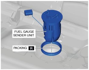
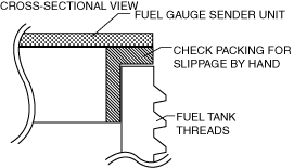
10. Remove the fuel gauge sender unit. (See Fuel gauge sender unit installation note.)
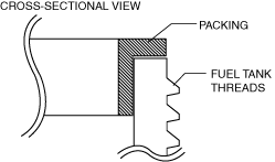
11. Remove the packing. (See Packing installation note.)
12. Install in the reverse order of removal.
13. Perform the fuel leakage inspection referring to “AFTER SERVICE PRECAUTION”. (See AFTER SERVICE PRECAUTION [SKYACTIV-D 1.5].)
Packing installation note
1. Install the packing so that it is adhered around the entire fuel tank opening.
Fuel gauge sender unit installation note
1. After installing the fuel gauge sender unit, verify by hand that the packing is installed correctly all the way around without any slippage.
Fuel gauge sender unit cap installation note
-
Note
-
• The fuel gauge sender unit will rotate and cannot be secured in the specified position if there is any gasoline on the packing. Thoroughly wipe away all gasoline from the packing.
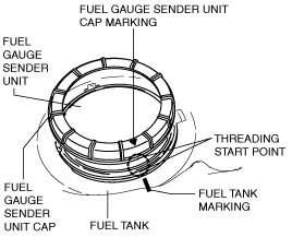
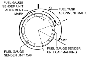
• Make the markings to be easily visible when the fuel gauge sender unit cap is installed.
• Marks are provided on the fuel gauge sender unit and fuel tank for correct installation of the fuel gauge sender unit.
• Tighten the fuel gauge sender unit cap using a torque wrench to prevent fuel leakage.
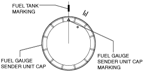
1. Mark the fuel gauge sender unit cap and the fuel tank at the point where the threading of each part begins as shown in the figure.
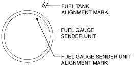
2. Align the fuel tank alignment mark with the fuel gauge sender unit as shown in the figure.
3. Align the fuel tank and fuel gauge sender unit cap markings.
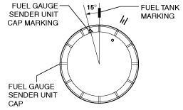
4. Rotate the fuel gauge sender unit cap counterclockwise until the cap marking is approx. 15° away from the fuel tank marking as shown in the figure.
-
Caution
-
• The cap could be damaged if the SST (wrench) is used with any play between the cap and the SST (wrench). Securely install the SST (wrench) so that there is no gap between the SST (wrench) tabs and the side of the cap.
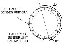
5. While keeping the fuel gauge sender unit from rising up, tighten the fuel gauge sender unit cap by hand 180 ° clockwise.
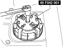
6. Set the SST (wrench) as shown in the figure.
7. Using a torque wrench, tighten the fuel gauge sender unit cap with both of the following specified rotation angle and specified torque met being careful not to shift the marks on the fuel gauge sender unit and fuel tank.
-
Caution
-
• To avoid exceeding the specified rotation angle due to excessive torque, tighten the fuel gauge sender unit cap starting from the minimum value of 50 N·m {5.1 kgf·m, 37 ft·lbf} and gradually increase the tightening torque without exceeding the maximum value of 140 N·m {14 kgf·m, 103 ft·lbf}, and secure the specified rotation angle of 270—315°.
-
Fuel gauge sender unit cap tightening torque
-
50—140 N·m {5.1—14 kgf·m, 37—103 ft·lbf}
-
• If the specified tightening torque cannot be obtained, replace the fuel gauge sender unit cap and packing.
• If the specified tightening torque cannot be obtained after replacement of the fuel gauge sender unit cap and packing, replace the fuel tank.
-
Note
-
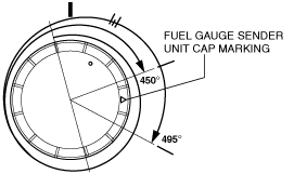
• The total rotation angle is 450—495 ° if the approx.180 ° from Step 5 is included.