 |
am3zzw00014926
CAPACITOR (i-ELOOP) REMOVAL/INSTALLATION [i-ELOOP]
id131704006000
Procedure Before i-ELOOP-Related Part Servicing
Cautions On Handling Capacitor (i-ELOOP)
Capacitor (i-ELOOP) Removal/Installation
1. Disconnect the negative battery cable. (See NEGATIVE BATTERY CABLE DISCONNECTION/CONNECTION.)
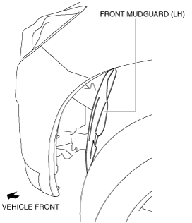
2. Set the front mudguard (LH) aside as shown in the figure. (See MUDGUARD REMOVAL/INSTALLATION.)
am3zzw00014926
|
3. Disconnect the service plug. (See SERVICE PLUG DISCONNECTION/CONNECTION [i-ELOOP].)
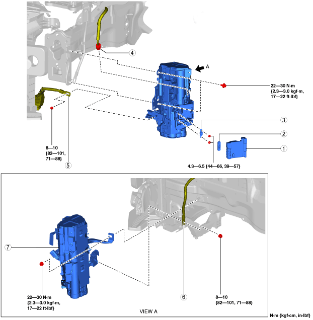
4. Remove in the order indicated in the table.
5. Install in the reverse order of removal.
6. When disposing of the capacitor (i-ELOOP), perform compulsory discharge of the capacitor before disposal. (See CAPACITOR (i-ELOOP) COMPULSORY DISCHARGE [i-ELOOP].)
7. If the capacitor is replaced with a new one, charge the new capacitor. (See CAPACITOR (i-ELOOP) RECHARGING [i-ELOOP].)
SKYACTIV-G 1.3, SKYACTIV-G 1.5
am2zzw00011512
|
|
1
|
Discharge box cover (for fuse removal/installation only)
|
|
2
|
Fuse cover (for fuse removal/installation only)
|
|
3
|
Fuse (for fuse removal/replacement only)
|
|
4
|
Capacitor connector, wiring harness
|
|
5
|
Engine wiring harness
|
|
6
|
Battery cable
|
|
7
|
Capacitor (i-ELOOP)
|
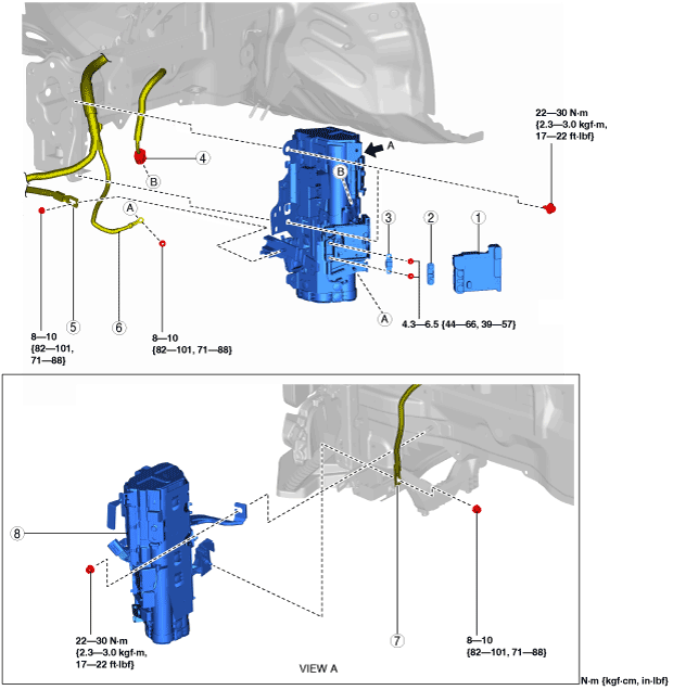
SKYACTIV-D 1.5
am2zzw00011513
|
|
1
|
Discharge box cover (for fuse removal/installation only)
|
|
2
|
Fuse cover (for fuse removal/installation only)
|
|
3
|
Fuse (for fuse removal/replacement only)
|
|
4
|
Capacitor connector, wiring harness
|
|
5
|
Engine wiring harness
|
|
6
|
Front wiring harness
|
|
7
|
Battery cable
|
|
8
|
Capacitor (i-ELOOP)
|
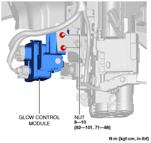
Engine wiring harness removal note (SKYACTIV-D 1.5)
1. Remove the nuts shown in the figure and set the glow control module aside so that access to the engine wiring harness is possible.
am2zzw00012361
|
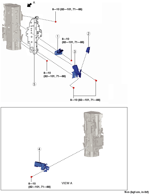
Capacitor Disassembly/Assembly
1. When replacing the capacitor with a new one, remove the following parts.
am2zzw00012362
|
|
1
|
Bracket
|
|
2
|
Terminal cover
|
|
3
|
Bus bar (DC-DC converter)
|
|
4
|
Bus bar (generator)
|
|
5
|
Front bracket
|
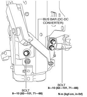
Bus bar (DC-DC converter) removal note
1. Remove the three bolts shown in the figure.
am2zzw00011516
|
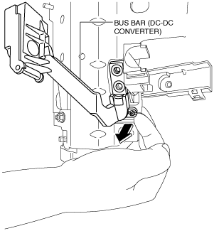
2. Remove the bus bar (DC-DC converter) by pressing it in the direction of the arrow shown in the figure.
am2zzw00011517
|
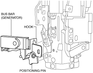
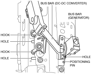
Bus bar (DC-DC converter), bus bar (generator) installation note
1. Insert the bus bar (generator) positioning pin and hook into the bracket.
am2zzw00011518
|
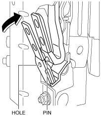
2. Move the bus bar (generator) in the direction of the arrow shown in the figure so that the capacitor terminal pin is inserted into the hole of the bus bar (generator).
am2zzw00011519
|
3. Align the hole of the bus bar (DC-DC converter) with the bus bar (generator) positioning pin while the bus bar (DC-DC converter) positioning hooks (2) are hooked with the bracket holes.
am2zzw00011520
|
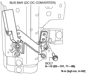
4. Tighten the bolts (2) shown in the figure.
am2zzw00011521
|
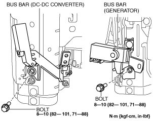
5. Tighten the bolts (2) shown in the figure.
am2zzw00011522
|
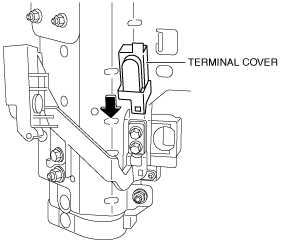
6. Install the terminal cover.
am2zzw00011523
|