DTC P2581:00 [SKYACTIV-D 1.5]


id0102q2448300

DTC P2581:00

Speed sensor assy. (turbocharger) circuit high input

DETECTION CONDITION
•  If the input voltage at the PCM terminal 1EJ is more than 2.5 V for 3.5 s, the PCM determines that the speed sensor assy. (turbocharger) circuit is high.
MONITORING CONDITIONS
―  0.5 s have elapsed after the engine was started.
Diagnostic support note
•  This is a continuous monitor (Turbo system).
•  The check engine light illuminates if the PCM detects the above malfunction condition during the first drive cycle.
•  FREEZE FRAME DATA/Snapshot data is available.
•  DTC is stored in the PCM memory.
FAIL-SAFE FUNCTION
•  Inhibits the EGR control.
•  Inhibits the auto diesel particulate filter regeneration control.
•  Inhibits engine-stop by operating the i-stop function.
POSSIBLE CAUSE
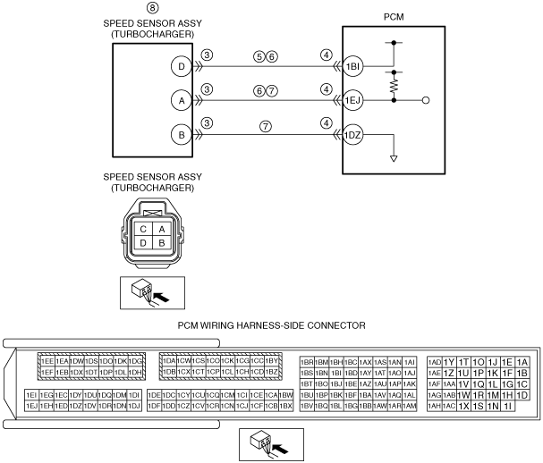
•  Speed sensor assy. (turbocharger) connector or terminals malfunction
•  PCM connector or terminals malfunction
•  Short to power supply in wiring harness between the following terminals:
―  Speed sensor assy. (turbocharger) terminal A—PCM terminal 1EJ
―  Speed sensor assy. (turbocharger) terminal B—PCM terminal 1DZ
•  PCM connector or terminals malfunction
•  Speed sensor assy. (turbocharger) power supply circuit and signal circuit are shorted to each other
•  Open circuit in wiring harness between the following terminals:
―  Speed sensor assy. (turbocharger) terminal A—PCM terminal 1EJ
―  Speed sensor assy. (turbocharger) terminal B—PCM terminal 1DZ
•  Speed sensor assy. (turbocharger) malfunction
•  PCM malfunction

Diagnostic Procedure

STEP

INSPECTION

ACTION

1
RECORD VEHICLE STATUS WHEN DTC WAS DETECTED TO UTILIZE WITH REPEATABILITY VERIFICATION
Note
•  Recording can be facilitated using the screen capture of the PC function.
•  Record the freeze frame data/snap shot data.
Go to the next step.
2
VERIFY RELATED SERVICE INFORMATION AVAILABILITY
•  Verify related Service Information availability.
•  Is any related Service Information available?
Yes
Perform repair or diagnosis according to the available Service Information.
•  If the vehicle is not repaired, go to the next step.
No
Go to the next step.
3
INSPECT SPEED SENSOR ASSY. (TURBOCHARGER) CONNECTOR CONDITION
•  Switch the ignition off.
•  Disconnect the speed sensor assy. (turbocharger) connector.
•  Inspect for poor connection (such as damaged/pulled-out pins, corrosion).
•  Is there any malfunction?
Yes
Repair or replace the connector and/or terminals, then go to Step 9.
No
Go to the next step.
4
INSPECT PCM CONNECTOR CONDITION
•  Disconnect the PCM connector.
•  Inspect for poor connection (such as damaged/pulled-out pins, corrosion).
•  Is there any malfunction?
Yes
Repair or replace the connector and/or terminals, then go to Step 9.
No
Go to the next step.
5
INSPECT SPEED SENSOR ASSY. (TURBOCHARGER)
•  Reconnect all disconnected connectors.
•  Inspect the speed sensor assy. (turbocharger).
•  Is there any malfunction?
Yes
Replace the speed sensor assy. (turbocharger), then go to the next step.
No
Go to the next step.
6
VERIFY DTC TROUBLESHOOTING COMPLETED
•  Always reconnect all disconnected connectors.
•  Clear the DTC from the PCM memory using the M-MDS.
•  Perform the KOER self test.
•  Is the same DTC present?
Yes
Repeat the inspection from Step 1.
•  If the malfunction recurs, replace the PCM.
Go to the next step.
No
Go to the next step.
7
VERIFY AFTER REPAIR PROCEDURE
•  Perform the “AFTER REPAIR PROCEDURE”.
•  Are any DTCs present?
Yes
Go to the applicable DTC inspection.
No
DTC troubleshooting completed.