 |
am2zzw00011036
HYDRAULIC VARIABLE VALVE TIMING ACTUATOR INSPECTION [SKYACTIV-G 1.3, SKYACTIV-G 1.5]
id0110q3126800
1. Disconnect the negative battery cable. (See NEGATIVE BATTERY CABLE DISCONNECTION/CONNECTION.)
2. Remove the plug hole plate. (See PLUG HOLE PLATE REMOVAL/INSTALLATION [SKYACTIV-G 1.3, SKYACTIV-G 1.5].)
3. Remove the ignition coils. (SKYACTIV-G 1.3, SKYACTIV-G 1.5 (with 4-1 exhaust system)) (See IGNITION COIL/ION SENSOR REMOVAL/INSTALLATION [SKYACTIV-G 1.3, SKYACTIV-G 1.5].)
4. Remove the ignition coil/ion sensors. (SKYACTIV-G 1.5 (with 4-2-1 exhaust system)) (See IGNITION COIL/ION SENSOR REMOVAL/INSTALLATION [SKYACTIV-G 1.3, SKYACTIV-G 1.5].)
5. Remove the cylinder head cover. (See TIMING CHAIN REMOVAL/INSTALLATION [SKYACTIV-G 1.3, SKYACTIV-G 1.5].)
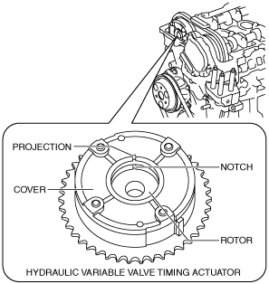
6. Verify that the notch of the rotor and projection of the cover on the hydraulic variable valve timing actuator are aligned and fitted. (Hydraulic variable valve timing actuator (type A))
SKYACTIV-G 1.3, SKYACTIV-G 1.5 (with 4-1 exhaust system)
am2zzw00011036
|
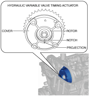
SKYACTIV-G 1.5 (with 4-2-1 exhaust system)
am3uuw00008881
|
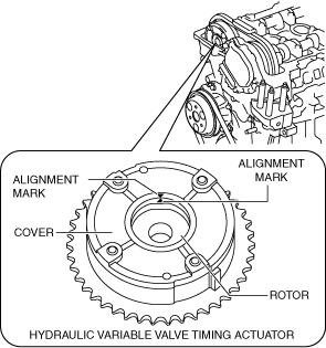
7. Verify that the alignment mark of the rotor and alignment mark of the cover on the hydraulic variable valve timing actuator are aligned and fitted. (Hydraulic variable valve timing actuator (type B))
SKYACTIV-G 1.5 (with 4-2-1 exhaust system)
ac5uuw00008995
|
8. Install in the reverse order of removal.