 |
am2zzw00011793
FUEL TANK REMOVAL/INSTALLATION [SKYACTIV-G 1.3, SKYACTIV-G 1.5]
id0114q1801600
1. Level the vehicle.
2. Complete the “BEFORE SERVICE PRECAUTION”. (See BEFORE SERVICE PRECAUTION [SKYACTIV-G 1.3, SKYACTIV-G 1.5].)
3. Drain the fuel. (See FUEL DRAINING PROCEDURE [SKYACTIV-G 1.3, SKYACTIV-G 1.5].)
4. Remove the rear seat cushion. (See REAR SEAT CUSHION REMOVAL/INSTALLATION.)
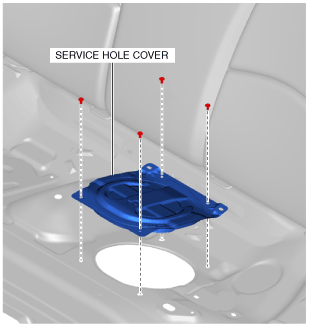
5. Remove the service hole cover.
am2zzw00011793
|
6. Disconnect the following parts:
7. Remove the fuel tank side cover. (See FUEL TANK SIDE COVER REMOVAL/INSTALLATION.)
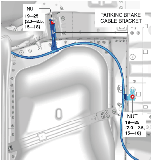
8. Remove the parking brake cable bracket (RH) nuts shown in the figure and set the parking brake cable bracket aside in a location that does not interfere with the servicing.
am2zzw00012847
|
9. Disconnect the HO2S connector.
10. Remove the TWC and HO2S as a single unit. (See EXHAUST SYSTEM REMOVAL/INSTALLATION [SKYACTIV-G 1.3, SKYACTIV-G 1.5].)
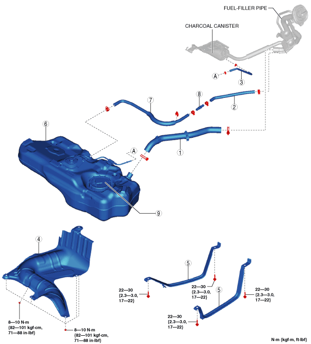
11. Remove in the order indicated in the table.
12. Install in the reverse order of removal.
13. Complete the “AFTER SERVICE PRECAUTION”. (See AFTER SERVICE PRECAUTION [SKYACTIV-G 1.3, SKYACTIV-G 1.5].)
am2zzw00011795
|
|
1
|
Joint hose
(See Joint Hose Installation Note.)
|
|
2
|
Breather hose No.1
|
|
3
|
Evaporative hose
|
|
4
|
Fuel tank insulator
|
|
5
|
Fuel tank strap
|
|
6
|
Fuel tank
(See Fuel Tank Removal Note.)
|
|
7
|
Breather hose No.2
|
|
8
|
Joint pipe
|
|
9
|
Fuel pump unit
|
Fuel Tank Removal Note
1. Remove the following parts as single unit:
2. Remove the fuel tank.
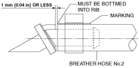
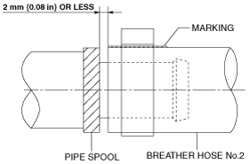
Breather Hose No.2 Installation Note
1. Install the breather hose No.2 as shown in the figure.
Fuel tank side
am2zzw00012848
|
Joint pipe side
am2zzw00012849
|
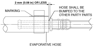
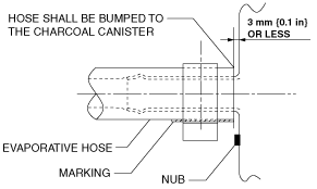
Evaporative Hose Installation Note
1. Install the evaporative hose as shown in the figure.
Fuel tank side
am2zzw00012850
|
Charcoal canister side
am2zzw00012851
|
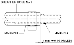
Breather Hose No.1 Installation Note
1. Install the breather hose No.1 as shown in the figure.
Fuel tank side
am2zzw00012852
|
Fuel-filler pipe side
am2zzw00012853
|
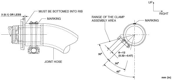
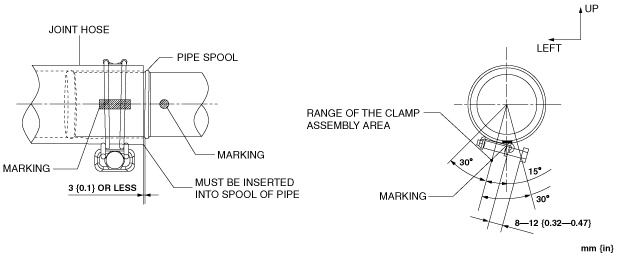
Joint Hose Installation Note
1. Install the joint hose as shown in the figure.
Fuel tank side
am2zzw00011802
|
Fuel-filler pipe side
am2zzw00011803
|