i-stop OFF SWITCH INSPECTION [SKYACTIV-G 1.3, SKYACTIV-G 1.5]
id0140q1888900
-
Note
-
• The i-stop OFF switch is integrated with the cluster switch.
Resistance Inspection
1. Disconnect the negative battery cable. (See NEGATIVE BATTERY CABLE DISCONNECTION/CONNECTION.)
2. Remove the following parts:
- (1) Driver-side front scuff plate (See FRONT SCUFF PLATE REMOVAL/INSTALLATION.)
- (2) Driver-side front side trim (See FRONT SIDE TRIM REMOVAL/INSTALLATION.)
- (3) Driver-side lower panel (See DRIVER-SIDE LOWER PANEL REMOVAL/INSTALLATION.)
- (4) Cluster switch (See CLUSTER SWITCH REMOVAL/INSTALLATION.)
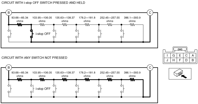
3. Measure the resistance between cluster switch terminals B and C under the following conditions.
-
Resistance with i-stop OFF switch pressed and held
-
• 83.66—85.34 ohms
-
Resistance with any switch not pressed
-
• 1,139.99—1,163.01 ohms
-
LED Illumination Inspection
1. Disconnect the negative battery cable. (See NEGATIVE BATTERY CABLE DISCONNECTION/CONNECTION.)
2. Remove the following parts:
- (1) Driver-side front scuff plate (See FRONT SCUFF PLATE REMOVAL/INSTALLATION.)
- (2) Driver-side front side trim (See FRONT SIDE TRIM REMOVAL/INSTALLATION.)
- (3) Driver-side lower panel (See DRIVER-SIDE LOWER PANEL REMOVAL/INSTALLATION.)
- (4) Cluster switch (See CLUSTER SWITCH REMOVAL/INSTALLATION.)
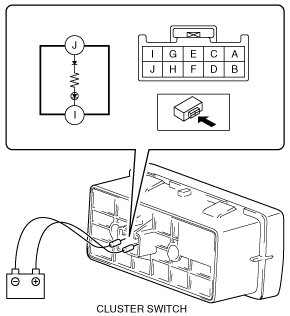
3. Apply battery positive voltage to cluster switch terminal J, and connect terminal I to ground.
4. Verify that the LED is turned on.
-