 |
am2zzw00011339
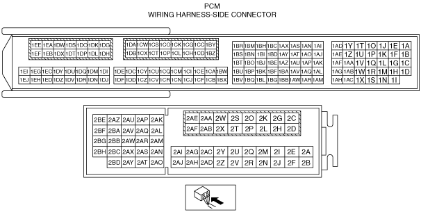
PCM INSPECTION [SKYACTIV-D 1.5]
id0140q2113900
Terminal voltage table (Reference)
am2zzw00011339
|
|
Terminal |
Signal |
Connected to |
Test condition |
Voltage (V) |
Inspection item |
|
|---|---|---|---|---|---|---|
|
1A
|
CMP (G+)
|
CMP sensor
|
(See CMP (G+) signal.)
|
• CMP sensor
• Related wiring harness
|
||
|
1B
|
CMP (G−)
|
CMP sensor
|
Switch ignition off
|
0
|
• CMP sensor
• Related wiring harness
|
|
|
Switch ignition ON (engine off)
|
Approx. 0.02
|
|||||
|
1C*1
|
CAN2_L
|
CAN system related modules
|
Because this terminal is for CAN, good/no good judgment by terminal voltage is not possible.
|
• Related wiring harness
|
||
|
1D
|
GND
|
Exhaust gas pressure sensor No.2
|
Switch ignition ON (engine off)
|
Approx. 0.02
|
• Related wiring harness
|
|
|
1E
|
CKP (NE+)
|
CKP sensor
|
(See CKP (NE+) signal.)
|
• CKP sensor
• Related wiring harness
|
||
|
1F
|
CKP (NE−)
|
CKP sensor
|
Switch ignition ON (engine off)
|
Approx. 0.01
|
• CKP sensor
• Related wiring harness
|
|
|
1G*1
|
CAN2_H
|
CAN system related modules
|
Because this terminal is for CAN, good/no good judgment by terminal voltage is not possible.
|
• Related wiring harness
|
||
|
1H
|
A/F (+)
|
A/F sensor
|
Idle (after warm up)
|
Approx. 3.04
|
• A/F sensor
• Related wiring harness
|
|
|
1I
|
A/F (−)
|
A/F sensor
|
Idle (after warm up)
|
Approx. 2.50
|
• A/F sensor
• Related wiring harness
|
|
|
1J
|
Constant voltage (Vref)
|
CKP sensor
|
Switch ignition ON (engine off)
|
Approx. 5.01
|
• Related wiring harness
|
|
|
1K
|
Constant voltage (Vref)
|
CMP sensor
|
Switch ignition ON (engine off)
|
Approx. 5.01
|
• Related wiring harness
|
|
|
1L
|
GND
|
Sensor shield
|
Switch ignition ON (engine off)
|
Approx. 0.01
|
• Related wiring harness
|
|
|
1M
|
—
|
—
|
—
|
—
|
—
|
|
|
1N
|
Boost air temperature
|
Boost air temperature sensor
|
Switch ignition ON (engine off)
|
Approx. 3.14
|
• Boost air temperature sensor
• Related wiring harness
|
|
|
1O*3
|
Generator output voltage
|
Generator
|
• Generator
• Related wiring harness
|
|||
|
1P
|
Blow-by heater relay
|
Blow-by heater relay
|
Switch ignition ON (engine off)
|
Approx. 0.09
|
• Blow-by heater relay
• Related wiring harness
|
|
|
Idle (after warm up)
|
Approx. 0.10
|
|||||
|
1Q
|
LIN
|
Glow control module, engine oil level sensor*5
|
Because this terminal is for CAN, good/no good judgment by terminal voltage is not possible.
|
• Glow control module
• engine oil level sensor*5
• Related wiring harness
|
||
|
1R
|
—
|
—
|
—
|
—
|
—
|
|
|
1S
|
—
|
—
|
—
|
—
|
—
|
|
|
1T
|
—
|
—
|
—
|
—
|
—
|
|
|
1U
|
—
|
—
|
—
|
—
|
—
|
|
|
1V
|
—
|
—
|
—
|
—
|
—
|
|
|
1W
|
Engine oil temperature
|
Engine oil temperature sensor
|
Switch ignition ON (engine off)
|
Approx. 2.04
|
• Engine oil temperature sensor
• Related wiring harness
|
|
|
1X
|
Exhaust gas pressure
|
Exhaust gas pressure sensor No.1
|
Switch ignition ON (engine off)
|
Approx. 0.96
|
• Exhaust gas pressure sensor No.1
• Related wiring harness
|
|
|
Idle (after warm up)
|
1.06—1.08
|
|||||
|
1Y
|
—
|
—
|
—
|
—
|
—
|
|
|
1Z
|
—
|
—
|
—
|
—
|
—
|
|
|
1AA
|
Constant voltage (Vref)
|
Exhaust gas pressure sensor No.2
|
Switch ignition ON (engine off)
|
Approx. 5.01
|
• Related wiring harness
|
|
|
1AB
|
Engine oil pressure
|
Engine oil pressure sensor
|
Switch ignition ON (engine off)
|
Approx. 0.512
|
• Engine oil pressure sensor
• Related wiring harness
|
|
|
Idle (after warm up)
|
1.14—1.15
|
|||||
|
1AC
|
Exhaust gas pressure
|
Exhaust gas pressure sensor No.2
|
Switch ignition ON (engine off)
|
Approx. 0.50
|
• Exhaust gas pressure sensor No.2
• Related wiring harness
|
|
|
Idle (after warm up)
|
0.59—0.60
|
|||||
|
1AD
|
A/F sensor heater control
|
A/F sensor heater
|
• A/F sensor heater
• Related wiring harness
|
|||
|
1AE
|
—
|
—
|
—
|
—
|
—
|
|
|
1AF
|
Constant voltage (Vref)
|
Fuel pressure sensor
|
Switch ignition ON (engine off)
|
Approx. 5.01
|
• Related wiring harness
|
|
|
1AG
|
Fuel pressure
|
Fuel pressure sensor
|
Switch ignition ON (engine off)
|
Approx. 0.52
|
• Fuel pressure sensor
• Related wiring harness
|
|
|
Idle (after warm up)
|
1.04—1.06
|
|||||
|
1AH
|
GND
|
Fuel pressure sensor
|
Switch ignition ON (engine off)
|
Approx. 0.01
|
• Related wiring harness
|
|
|
1AI
|
LP-EGR control valve (LPEGR−)
|
LP-EGR control valve
|
Switch ignition ON (engine off)
|
Approx. 12.67
|
• LP-EGR control valve
• Related wiring harness
|
|
|
1AJ
|
Exhaust shutter valve (ESV−)
|
Exhaust shutter valve
|
Switch ignition ON (engine off)
|
Approx. 12.66
|
• Exhaust shutter valve
• Related wiring harness
|
|
|
(See Exhaust shutter valve (ESV-).)
|
||||||
|
1AK
|
Constant voltage (Vref)
|
Exhaust shutter valve position sensor
|
Switch ignition ON (engine off)
|
Approx. 5.01
|
• Related wiring harness
|
|
|
1AL
|
Exhaust shutter valve position
|
Exhaust shutter valve position sensor
|
Switch ignition ON (engine off)
|
Approx. 4.28
|
• Exhaust shutter valve position sensor
• Related wiring harness
|
|
|
Idle (after warm up)
|
Approx. 4.06
|
|||||
|
1AM
|
GND
|
Exhaust shutter valve position sensor
|
Switch ignition ON (engine off)
|
Approx. 0.01
|
• Related wiring harness
|
|
|
1AN
|
LP-EGR control valve (LPEGR+)
|
LP-EGR control valve
|
Switch ignition ON (engine off)
|
Approx. 12.62
|
• LP-EGR control valve
• Related wiring harness
|
|
|
Idle
|
Approx. 14.29
|
|||||
|
1AO
|
Exhaust shutter valve (ESV+)
|
Exhaust shutter valve
|
Switch ignition ON (engine off)
|
Approx. 12.61
|
• Exhaust shutter valve
• Related wiring harness
|
|
|
Idle
|
Approx. 14.28
|
|||||
|
1AP
|
Constant voltage (Vref)
|
LP-EGR control valve position sensor
|
Switch ignition ON (engine off)
|
Approx. 5.01
|
• Related wiring harness
|
|
|
1AQ
|
LP-EGR control valve position
|
LP-EGR control valve position sensor
|
Switch ignition ON (engine off)
|
Approx. 1.20
|
• LP-EGR control valve position sensor
• Related wiring harness
|
|
|
Idle (after warm up)
|
1.29—1.31
|
|||||
|
1AR
|
GND
|
LP-EGR control valve position sensor
|
Switch ignition ON (engine off)
|
Approx. 0.01
|
• Related wiring harness
|
|
|
1AS
|
Intake shutter valve (ISV-)
|
Intake shutter valve
|
Switch ignition ON (engine off)
|
Approx. 12.54
|
• Intake shutter valve
• Related wiring harness
|
|
|
1AT
|
—
|
—
|
—
|
—
|
—
|
|
|
1AU
|
Constant voltage (Vref)
|
Intake shutter valve position sensor
|
Switch ignition ON (engine off)
|
Approx. 5.01
|
• Related wiring harness
|
|
|
1AV
|
Intake shutter valve position
|
Intake shutter valve position sensor
|
Switch ignition ON (engine off)
|
Approx. 4.17
|
• Intake shutter valve position sensor
• Related wiring harness
|
|
|
Idle (after warm up)
|
0.71—0.72
|
|||||
|
1AW
|
GND
|
Intake shutter valve position sensor
|
Switch ignition ON (engine off)
|
Approx. 0.01
|
• Related wiring harness
|
|
|
1AX
|
Intake shutter valve (ISV+)
|
Intake shutter valve
|
Switch ignition ON (engine off)
|
Approx. 12.51
|
• Intake shutter valve
• Related wiring harness
|
|
|
Idle
|
Approx. 14.15
|
|||||
|
1AY*4
|
Generator field coil control
|
Generator
|
• Generator
• Related wiring harness
|
|||
|
1AZ
|
Constant voltage (Vref)
|
MAP sensor, boost air temperature sensor
|
Switch ignition ON (engine off)
|
Approx. 5.01
|
• Related wiring harness
|
|
|
1BA
|
MAP
|
MAP sensor
|
Switch ignition ON (engine off)
|
Approx. 1.63
|
• MAP sensor
• Related wiring harness
|
|
|
Idle (after warm up)
|
1.50—1.52
|
|||||
|
1BB
|
GND
|
MAP sensor, boost air temperature sensor
|
Switch ignition ON (engine off)
|
Approx. 0.02
|
• Related wiring harness
|
|
|
1BC
|
HP-EGR control valve (EGRH−)
|
HP-EGR control valve
|
Switch ignition ON (engine off)
|
Approx. 12.89
|
• HP-EGR control valve
• Related wiring harness
|
|
|
Idle (when cold)
|
Approx. 13.00
|
|||||
|
Idle (after warm up)
|
Approx. 13.25
|
|||||
|
1BD
|
—
|
—
|
—
|
—
|
—
|
|
|
1BE
|
Constant voltage (Vref)
|
HP-EGR control valve position sensor
|
Switch ignition ON (engine off)
|
Approx. 5.01
|
• Related wiring harness
|
|
|
1BF
|
HP-EGR control valve position
|
HP-EGR control valve position sensor
|
Switch ignition ON (engine off)
|
Approx. 1.21
|
• HP-EGR control valve
• Related wiring harness
|
|
|
Idle (after warm up)
|
Approx. 2.06
|
|||||
|
1BG
|
GND
|
HP-EGR control valve position sensor
|
Switch ignition ON (engine off)
|
Approx. 0.01
|
• Related wiring harness
|
|
|
1BH
|
HP-EGR control valve (EGRH+)
|
HP-EGR control valve
|
Switch ignition ON (engine off)
|
Approx. 12.78
|
• HP-EGR control valve
• Related wiring harness
|
|
|
1BI
|
Constant voltage (Vref)
|
Speed sensor assy (turbocharger with variable turbine geometry)
|
Switch ignition ON (engine off)
|
Approx. 5.01
|
• Related wiring harness
|
|
|
Idle (after warm up)
|
Approx. 5.10
|
|||||
|
1BJ
|
Constant voltage (Vref)
|
Actuator position sensor (turbocharger with variable turbine geometry)
|
Switch ignition ON (engine off)
|
Approx. 5.01
|
• Related wiring harness
|
|
|
1BK
|
Actuator position
|
Actuator position sensor (turbocharger with variable turbine geometry)
|
Switch ignition ON (engine off)
|
Approx. 0.58
|
• Actuator position sensor (turbocharger with variable turbine geometry)
• Related wiring harness
|
|
|
Idle (after warm up)
|
Approx. 3.38
|
|||||
|
1BL
|
GND
|
Actuator position sensor (turbocharger with variable turbine geometry)
|
Switch ignition ON (engine off)
|
Approx. 0.01
|
• Related wiring harness
|
|
|
1BM
|
Coolant control valve (3WAY−)
|
Coolant control valve
|
Switch ignition ON (engine off)
|
Approx. 12.72
|
• Coolant control valve
• Related wiring harness
|
|
|
Idle (when cold)
|
Approx. 14.34
|
|||||
|
Idle (after warm up)
|
Approx. 14.33
|
|||||
|
1BN
|
—
|
—
|
—
|
—
|
—
|
|
|
1BO
|
Constant voltage (Vref)
|
Coolant control valve position sensor
|
Switch ignition ON (engine off)
|
Approx. 5.01
|
• Related wiring harness
|
|
|
1BP
|
Coolant control valve position
|
Coolant control valve position sensor
|
Switch ignition ON (engine off)
|
Approx. 4.53
|
• Coolant control valve
• Related wiring harness
|
|
|
Idle (after warm up)
|
1.60—1.62
|
|||||
|
1BQ
|
GND
|
Coolant control valve position sensor
|
Switch ignition ON (engine off)
|
Approx. 0.01
|
• Related wiring harness
|
|
|
1BR
|
Coolant control valve (3WAY+)
|
Coolant control valve
|
Switch ignition ON (engine off)
|
Approx. 12.68
|
• Coolant control valve
• Related wiring harness
|
|
|
1BS
|
—
|
—
|
—
|
—
|
—
|
|
|
1BT
|
Constant voltage (Vref)
|
Engine oil temperature sensor, engine oil pressure sensor
|
Switch ignition ON (engine off)
|
Approx. 5.02
|
• Related wiring harness
|
|
|
1BU*4
|
Generator field coil control
|
Generator
|
• Generator
• Related wiring harness
|
|||
|
1BV
|
GND
|
Engine oil temperature sensor, engine oil pressure sensor
|
Switch ignition ON (engine off)
|
Approx. 0.01
|
• Related wiring harness
|
|
|
1BW
|
Exhaust gas temperature
|
Exhaust gas temperature sensor No.3
|
Switch ignition ON (engine off)
|
Approx. 4.78
|
• Exhaust gas temperature sensor No.3
• Related wiring harness
|
|
|
1BX
|
GND
|
Exhaust gas temperature sensor No.3
|
Under any condition
|
Approx. 0.01
|
• Related wiring harness
|
|
|
1BY
|
Suction control valve
|
Suction control valve
|
Switch ignition ON (engine off)
|
Approx. 0.01
|
• Suction control valve
• Related wiring harness
|
|
|
Idle (after warm up)
|
0.44—0.49
|
|||||
|
1BZ
|
GND
|
GND
|
Switch ignition ON (engine off)
|
Approx. 0.01
|
• Related wiring harness
|
|
|
1CA
|
Exhaust gas temperature
|
Exhaust gas temperature sensor No.2
|
Switch ignition ON (engine off)
|
Approx. 4.70
|
• Exhaust gas temperature sensor No.2
• Related wiring harness
|
|
|
1CB
|
GND
|
Exhaust gas temperature sensor No.2
|
Switch ignition ON (engine off)
|
Approx. 0.01
|
• Related wiring harness
|
|
|
1CC
|
Suction control valve
|
Suction control valve
|
Switch ignition ON (engine off)
|
Approx. 0.01
|
• Suction control valve
• Related wiring harness
|
|
|
(See Suction control valve signal.)
|
||||||
|
1CD
|
GND
|
GND
|
Switch ignition ON (engine off)
|
Approx. 0.01
|
• Related wiring harness
|
|
|
1CE
|
Exhaust gas temperature
|
Exhaust gas temperature sensor No.4
|
Switch ignition ON (engine off)
|
Approx. 4.96
|
• Exhaust gas temperature sensor No.4
• Related wiring harness
|
|
|
1CF
|
GND
|
Exhaust gas pressure sensor No.1
|
Switch ignition ON (engine off)
|
Approx. 0.01
|
• Related wiring harness
|
|
|
1CG*3
|
Generator field coil control
|
Generator
|
• Generator
• Related wiring harness
|
|||
|
1CH
|
Turbocharger solenoid valve
|
Turbocharger solenoid valve
|
Switch ignition ON (engine off)
|
Approx. 12.38
|
• Turbocharger solenoid valve
• Related wiring harness
|
|
|
(See Turbocharger solenoid valve.)
|
||||||
|
1CI
|
Exhaust gas temperature
|
Exhaust gas temperature sensor No.1
|
Switch ignition ON (engine off)
|
Approx. 4.98
|
• Exhaust gas temperature sensor No.1
• Related wiring harness
|
|
|
1CJ
|
Constant voltage (Vref)
|
Exhaust gas pressure sensor No.1
|
Switch ignition ON (engine off)
|
Approx. 5.01
|
• Related wiring harness
|
|
|
1CK
|
—
|
—
|
—
|
—
|
—
|
|
|
1CL
|
—
|
—
|
—
|
—
|
—
|
|
|
1CM
|
—
|
—
|
—
|
—
|
—
|
|
|
1CN
|
GND
|
Exhaust gas temperature sensor No.1
|
Switch ignition ON (engine off)
|
Approx. 0.01
|
• Related wiring harness
|
|
|
1CO
|
Engine oil control
|
Engine oil solenoid valve
|
Switch ignition ON (engine off)
|
Approx. 12.37
|
• Engine oil solenoid valve
• Related wiring harness
|
|
|
(See Engine oil control signal.)
|
||||||
|
1CP
|
Electric water pump
|
Electric water pump
|
Switch ignition ON (engine off)
|
Approx. 0.02
|
• Electric water pump
• Related wiring harness
|
|
|
1CQ
|
IAT (No.2)
|
IAT sensor No.2
|
Switch ignition ON (engine off)
|
Approx. 2.52
|
• IAT sensor No.2
• Related wiring harness
|
|
|
1CR
|
GND
|
IAT sensor No.2
|
Switch ignition ON (engine off)
|
Approx. 0.01
|
• Related wiring harness
|
|
|
1CS
|
Fuel injection control (+)
|
Fuel injector No.3
|
• Fuel injector No.3
• Related wiring harness
|
|||
|
1CT
|
Fuel injection control (+)
|
Fuel injector No.2
|
• Fuel injector No.2
• Related wiring harness
|
|||
|
1CU
|
Fuel temperature
|
Fuel temperature sensor
|
Switch ignition ON (engine off)
|
Approx. 1.97
|
• Fuel temperature sensor
• Related wiring harness
|
|
|
1CV
|
GND
|
Fuel temperature sensor
|
Switch ignition ON (engine off)
|
Approx. 0.01
|
• Related wiring harness
|
|
|
1CW
|
Fuel injection control (−)
|
Fuel injector No.2
|
• Fuel injector No.2
• Related wiring harness
|
|||
|
1CX
|
—
|
—
|
—
|
—
|
—
|
|
|
1CY
|
ECT
|
ECT sensor
|
Switch ignition ON (engine off)
|
Approx. 2.02
|
• ECT sensor
• Related wiring harness
|
|
|
1CZ
|
GND
|
ECT sensor
|
Switch ignition ON (engine off)
|
Approx. 0.01
|
• Related wiring harness
|
|
|
1DA
|
Fuel injection control (−)
|
Fuel injector No.3
|
• Fuel injector No.3
• Related wiring harness
|
|||
|
1DB
|
—
|
—
|
—
|
—
|
—
|
|
|
1DC
|
—
|
—
|
—
|
—
|
—
|
|
|
1DD
|
—
|
—
|
—
|
—
|
—
|
|
|
1DE
|
—
|
—
|
—
|
—
|
—
|
|
|
1DF
|
GND
|
Sensor shield
|
Switch ignition ON (engine off)
|
Approx. 0.01
|
• Related wiring harness
|
|
|
1DG
|
PRD−
|
Fuel pressure relief valve
|
Switch ignition ON (engine off)
|
Approx. 2.58
|
• Fuel pressure relief valve
• Related wiring harness
|
|
|
Idle (after warm up)
|
Approx. 2.65
|
|||||
|
1DH
|
Battery voltage
|
Main relay
|
Switch ignition ON (engine off)
|
B+
|
• Related wiring harness
|
|
|
1DI
|
—
|
—
|
—
|
—
|
—
|
|
|
1DJ
|
—
|
—
|
—
|
—
|
—
|
|
|
1DK
|
PRD+
|
Fuel pressure relief valve
|
Switch ignition ON (engine off)
|
Approx. 2.58
|
• Fuel pressure relief valve
• Related wiring harness
|
|
|
Idle (after warm up)
|
Approx. 2.66
|
|||||
|
1DL
|
Battery voltage
|
Main relay
|
Switch ignition ON (engine off)
|
B+
|
• Related wiring harness
|
|
|
1DM
|
—
|
—
|
—
|
—
|
—
|
|
|
1DN
|
—
|
—
|
—
|
—
|
—
|
|
|
1DO
|
—
|
—
|
—
|
—
|
—
|
|
|
1DP
|
—
|
—
|
—
|
—
|
—
|
|
|
1DQ
|
GND
|
Sensor shield
|
Switch ignition ON (engine off)
|
Approx. 0.01
|
• Related wiring harness
|
|
|
1DR
|
—
|
—
|
—
|
—
|
—
|
|
|
1DS
|
—
|
—
|
—
|
—
|
—
|
|
|
1DT
|
—
|
—
|
—
|
—
|
—
|
|
|
1DU
|
—
|
—
|
—
|
—
|
—
|
|
|
1DV
|
GND
|
Exhaust gas temperature sensor No.4
|
Switch ignition ON (engine off)
|
Approx. 0.01
|
• Related wiring harness
|
|
|
1DW
|
Fuel injection control (−)
|
Fuel injector No.4
|
• Fuel injector No.4
• Related wiring harness
|
|||
|
1DX
|
—
|
—
|
—
|
—
|
—
|
|
|
1DY
|
GND
|
Sensor shield
|
Switch ignition ON (engine off)
|
Approx. 0.01
|
• Related wiring harness
|
|
|
1DZ
|
GND
|
Speed sensor assy (turbocharger with variable turbine geometry)
|
Switch ignition ON (engine off)
|
Approx. 0.01
|
• Related wiring harness
|
|
|
1EA
|
Fuel injection control (−)
|
Fuel injector No.1
|
• Fuel injector No.1
• Related wiring harness
|
|||
|
1EB
|
—
|
—
|
—
|
—
|
—
|
|
|
1EC
|
GND
|
Sensor shield
|
Switch ignition ON (engine off)
|
Approx. 0.01
|
• Related wiring harness
|
|
|
1ED
|
—
|
—
|
—
|
—
|
—
|
|
|
1EE
|
Fuel injection control (+)
|
Fuel injector No.1
|
• Fuel injector No.1
• Related wiring harness
|
|||
|
1EF
|
Fuel injection control (+)
|
Fuel injector No.4
|
• Fuel injector No.4
• Related wiring harness
|
|||
|
1EG
|
—
|
—
|
—
|
—
|
—
|
|
|
1EH
|
—
|
—
|
—
|
—
|
—
|
|
|
1EI
|
—
|
—
|
—
|
—
|
—
|
|
|
1EJ
|
TURBINE ROTATION SPEED SIGNAL
|
Speed sensor assy (turbocharger with variable turbine geometry)
|
• Speed sensor assy (turbocharger with variable turbine geometry)
• Related wiring harness
|
|||
|
2A
|
—
|
—
|
—
|
—
|
—
|
|
|
2B*2
|
Neutral position
|
Neutral switch No.1
|
Shift lever is at neutral position
|
Below 1.0
|
• Neutral switch No.1
• Related wiring harness
|
|
|
Shift lever is not at neutral position
|
B+
|
|||||
|
2C
|
HS CAN_H
|
CAN system related modules
|
Because this terminal is for CAN, good/no good judgment by terminal voltage is not possible.
|
• Related wiring harness
|
||
|
2D
|
HS CAN_L
|
CAN system related modules
|
Because this terminal is for CAN, good/no good judgment by terminal voltage is not possible.
|
• Related wiring harness
|
||
|
2E
|
Check connector
|
Check connector
|
Switch ignition ON (engine off)
|
Approx. 12.83
|
• Check connector
• Related wiring harness
|
|
|
2F
|
—
|
—
|
—
|
—
|
—
|
|
|
2G*2
|
Neutral switch No.2
|
Neutral switch No.2
|
Switch ignition ON (engine off)
|
Neutral
|
Below 1.0
|
• Neutral switch No.2
• Related wiring harness
|
|
Except above
|
B+
|
|||||
|
2H
|
Ignition (IG1)
|
IG1 relay
|
Switch ignition ON (engine off)
|
Approx. 12.72
|
• IG1 relay
• Related wiring harness
|
|
|
2I
|
—
|
—
|
—
|
—
|
—
|
|
|
2J*2
|
Back-up light
|
Back-up light switch
|
Shift lever is at R position
|
Below 1.0
|
• Back-up light switch
• Related wiring harness
|
|
|
Shift lever is not at R position
|
B+
|
|||||
|
2K
|
Main relay control
|
Main relay
|
Switch ignition ON (engine off)
|
Approx. 0.85
|
• Main relay
• Related wiring harness
|
|
|
2L
|
—
|
—
|
—
|
—
|
—
|
|
|
2M*2
|
CPP
|
CPP switch, start stop unit
|
Clutch pedal depressed
|
Below 1.0
|
• CPP switch
• Start stop unit
• Related wiring harness
|
|
|
Clutch pedal released
|
B+
|
|||||
|
2N
|
Selector lever position*1
|
TCM, start stop unit
|
Selector lever position is not P or N position
|
R position: Approx. 12.32
|
• TCM
• Start stop unit
• Related wiring harness
|
|
|
M position: Approx. 12.45
|
||||||
|
D position: Approx. 12.48
|
||||||
|
Selector lever position is P or N position
|
P position: Approx. 0.17
|
|||||
|
N position: Approx. 0.17
|
||||||
|
Starter interlock*2
|
Starter interlock switch, start stop unit
|
Clutch pedal depressed
|
Below 1.0
|
• Starter interlock switch
• Start stop unit
• Related wiring harness
|
||
|
Clutch pedal released
|
B+
|
|||||
|
2O
|
Battery voltage
|
Battery
|
Switch ignition ON (engine off)
|
B+
|
• Related wiring harness
|
|
|
2P
|
DC-DC converter control*4
|
DC-DC converter
|
Switch ignition ON (engine off)
|
Below 1.0
|
• DC-DC converter
• Related wiring harness
|
|
|
DC-DC converter (i-ELOOP) control*3
|
DC-DC converter (i-ELOOP)
|
Switch ignition ON (engine off)
|
Below 1.0
|
• DC-DC converter (i-ELOOP)
• Related wiring harness
|
||
|
2Q
|
—
|
—
|
—
|
—
|
—
|
|
|
2R
|
—
|
—
|
—
|
—
|
—
|
|
|
2S
|
Battery voltage
|
Main relay
|
Switch ignition ON (engine off)
|
B+
|
• Related wiring harness
|
|
|
2T
|
Battery voltage
|
Main relay
|
Switch ignition ON (engine off)
|
B+
|
• Related wiring harness
|
|
|
2U
|
—
|
—
|
—
|
—
|
—
|
|
|
2V
|
GND
|
MAF sensor, IAT sensor No.1
|
Switch ignition ON (engine off)
|
Approx. 0.01
|
• Related wiring harness
|
|
|
2W
|
Blow-by heater relay
|
Blow-by heater relay
|
Switch ignition ON (engine off)
|
Approx. 12.58
|
• Blow-by heater relay
• Related wiring harness
|
|
|
Idle (after warm up)
|
14.45—14.52
|
|||||
|
2X
|
GND
|
GND
|
Switch ignition ON (engine off)
|
Approx. 0.01
|
• Related wiring harness
|
|
|
2Y
|
—
|
—
|
—
|
—
|
—
|
|
|
2Z
|
GND
|
Refrigerant pressure sensor
|
Switch ignition ON (engine off)
|
Approx. 0.01
|
• Related wiring harness
|
|
|
2AA
|
Brake (No.1)
|
Brake switch (No.1 signal)
|
Brake pedal released
|
Approx. 0.01
|
• Brake switch (No.1 signal)
• Related wiring harness
|
|
|
Brake pedal depressed
|
Approx. 12.47
|
|||||
|
2AB
|
Brake (No.2)
|
Brake switch (No.2 signal)
|
Brake pedal released
|
Approx. 0.01
|
• Brake switch (No.2 signal)
• Related wiring harness
|
|
|
Brake pedal depressed
|
Approx. 12.12
|
|||||
|
2AC
|
MAF
|
MAF sensor
|
Switch ignition ON (engine off)
|
Approx. 0.95
|
• MAF sensor
• Related wiring harness
|
|
|
Idle (after warm up)
|
1.34—1.36
|
|||||
|
2AD
|
GND
|
GND
|
Switch ignition ON (engine off)
|
Approx. 0.01
|
• Related wiring harness
|
|
|
2AE
|
GND
|
GND
|
Switch ignition ON (engine off)
|
Approx. 0.01
|
• Related wiring harness
|
|
|
2AF
|
GND
|
GND
|
Switch ignition ON (engine off)
|
Approx. 0.01
|
• Related wiring harness
|
|
|
2AG
|
Ambient temperature
|
Ambient temperature sensor
|
Switch ignition ON (engine off)
|
Approx. 2.06
|
• Ambient temperature sensor
• Related wiring harness
|
|
|
2AH*2
|
GND
|
Clutch stroke sensor
|
Under any condition
|
Below 1.0
|
• Related wiring harness
|
|
|
2AI
|
Constant voltage (Vref)
|
MAF sensor
|
Switch ignition ON (engine off)
|
Approx. 5.01
|
• Related wiring harness
|
|
|
2AJ*2
|
Clutch stroke sensor
|
Clutch stroke sensor
|
Switch ignition ON (engine off)
|
Clutch pedal released
|
Approx. 4.50
|
• Clutch stroke sensor
• Related wiring harness
|
|
Clutch pedal depressed
|
Approx. 0.83
|
|||||
|
2AK
|
Constant voltage (Vref)
|
Power brake unit vacuum sensor
|
Switch ignition ON (engine off)
|
Approx. 5.01
|
• Related wiring harness
|
|
|
2AL*2
|
Constant voltage (Vref)
|
Clutch stroke sensor
|
Switch ignition ON (engine off)
|
Approx. 5.01
|
• Related wiring harness
|
|
|
2AM
|
Constant voltage (Vref)
|
APP sensor No.1
|
Switch ignition ON (engine off)
|
Approx. 5.01
|
• Related wiring harness
|
|
|
2AN
|
APP (No.1)
|
APP sensor No.1
|
Switch ignition ON (engine off)
|
Accelerator pedal released
|
Approx. 0.80
|
• APP sensor No.1
• Related wiring harness
|
|
Accelerator pedal depressed
|
Approx. 4.57
|
|||||
|
2AO
|
GND
|
APP sensor No.1
|
Under any condition
|
Approx. 0.01
|
• Related wiring harness
|
|
|
2AP
|
—
|
—
|
—
|
—
|
—
|
|
|
2AQ
|
A/C cut-off control
|
A/C relay
|
A/C relay OFF
|
Approx. 14.52
|
• A/C relay
• Related wiring harness
|
|
|
A/C relay ON
|
Approx. 0.20
|
|||||
|
2AR
|
Constant voltage (Vref)
|
Refrigerant pressure sensor
|
Switch ignition ON (engine off)
|
Approx. 5.01
|
• Related wiring harness
|
|
|
2AS
|
IAT (No.1)
|
IAT sensor No.1
|
Switch ignition ON (engine off)
|
Approx. 1.96
|
• IAT sensor No.1
• Related wiring harness
|
|
|
2AT
|
GND
|
Ambient temperature sensor
|
Switch ignition ON (engine off)
|
Approx. 0.01
|
• Related wiring harness
|
|
|
2AU*3
|
DC-DC converter (i-ELOOP) control
|
DC-DC converter (i-ELOOP)
|
Idle (after warm up)
|
0 or B+
|
• DC-DC converter (i-ELOOP)
• Related wiring harness
|
|
|
2AV
|
—
|
—
|
—
|
—
|
—
|
|
|
2AW
|
Constant voltage (Vref)
|
APP sensor No.2
|
Switch ignition ON (engine off)
|
Approx. 5.01
|
• Related wiring harness
|
|
|
2AX
|
APP (No.2)
|
APP sensor No.2
|
Switch ignition ON (engine off)
|
Accelerator pedal released
|
Approx. 0.41
|
• APP sensor No.2
• Related wiring harness
|
|
Accelerator pedal depressed
|
Approx. 2.29
|
|||||
|
2AY
|
GND
|
APP sensor No.2
|
Switch ignition ON (engine off)
|
Approx. 0.01
|
• Related wiring harness
|
|
|
2AZ
|
Cooling fan control
|
Cooling fan relay
|
Cooling fan operating
|
Below 1.0
|
• Cooling fan relay
• Related wiring harness
|
|
|
Cooling fan not operating
|
B+
|
|||||
|
2BA
|
—
|
—
|
—
|
—
|
—
|
|
|
2BB
|
—
|
—
|
—
|
—
|
—
|
|
|
2BC
|
Power brake unit vacuum
|
Power brake unit vacuum sensor
|
Switch ignition ON (engine off)
|
Brake pedal depressed (10 times)
|
Approx. 3.98
|
• Power brake unit vacuum sensor
• Related wiring harness
|
|
Idle (after warm up)
|
Brake pedal released
|
0.41—0.42
|
||||
|
2BD
|
GND
|
Power brake unit vacuum sensor
|
Switch ignition ON (engine off)
|
Approx. 0.32
|
• Related wiring harness
|
|
|
2BE
|
—
|
—
|
—
|
—
|
—
|
|
|
2BF
|
Starter cut-off control
|
Starter relay, start stop unit
|
Switch ignition ON (engine off)
|
MTX
• Clutch pedal released
|
B+
|
• Starter relay
• Start stop unit
• Related wiring harness
|
|
ATX
• Selector lever position is not P or N position
|
R position: Approx. 11.14
|
|||||
|
D position: Approx. 11.23
|
||||||
|
M position: Approx. 11.23
|
||||||
|
MTX
• Clutch pedal depressed
|
Below 1.0
|
|||||
|
ATX
• Selector lever position is P or N position
|
P position: Approx. 0.01
|
|||||
|
N position: Approx. 0.01
|
||||||
|
2BG
|
Fan control
|
Fan control module
|
Switch ignition ON (engine off)
|
Approx. 0.61
|
• Fan control module
• Related wiring harness
|
|
|
2BH
|
Refrigerant pressure
|
Refrigerant pressure sensor
|
Switch ignition ON (engine off)
|
A/C switch off
|
Approx. 0.94
|
• Refrigerant pressure sensor
• Related wiring harness
|
|
Idle (after warm up) or switch ignition ON (engine off)
|
1.39—1.59
|
|||||
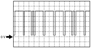
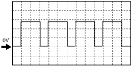
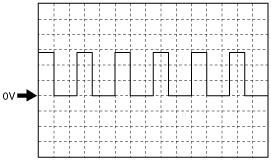
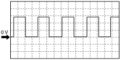
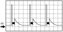
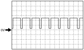
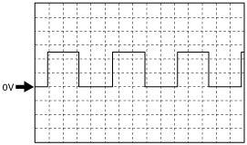
Inspection Using An Oscilloscope (Reference)
CMP (G+) signal
am2zzw00011340
|
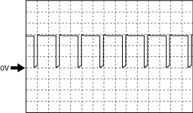
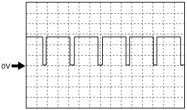
Intake shutter valve (ISV-) signal
am3zzw00012795
|
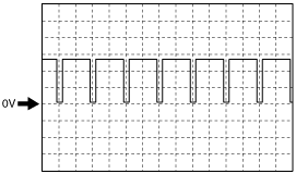
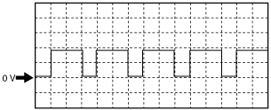
LP-EGR control valve (LPEGR-)
am2zzw00011341
|
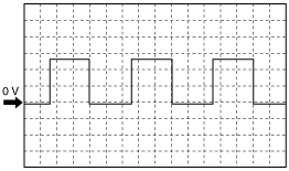
Suction control valve signal
am2zzw00011342
|
A/F sensor heater control signal
am2zzw00011343
|
Engine oil control signal
am2zzw00011344
|
Turbocharger solenoid valve
am2zzw00011345
|
Fuel injection control (-) signal
am2zzw00011346
|
Fuel injection control (+) signal
am2zzw00011346
|
Generator output voltage signal
am2zzw00011347
|
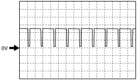
CKP (NE+) signal
am2zzw00011348
|
Generator field coil control signal
am2zzw00011349
|
Exhaust shutter valve (ESV-)
am2zzw00011350
|
TURBINE ROTATION SPEED SIGNAL
am2zzw00011351
|
Using The M-MDS
1. Connect the M-MDS to the DLC-2.
2. Switch the ignition ON (engine off).
3. Measure the PID value.
PID/DATA monitor item table
|
Item (definition) |
Unit/Condition |
Definition |
Value type |
Condition/Specification (Reference) |
PCM terminal |
|---|---|---|---|---|---|
|
AC_PRES
|
kPa, Bar, psi
|
Refrigerant pressure
|
Converted value
|
Idle
• A/C switch ON: Approx. 930 kPa {9.48 kgf/cm2, 135 psi}
|
2BH
|
|
AC_REQ
|
Off/On
|
A/C request signal
|
Converted value
|
• A/C switch OFF: Off
• A/C switch ON: On
|
CAN(2C, 2D)
|
|
ACCS
|
Off/On
|
A/C relay
|
Output
|
• A/C relay is OFF: Off
• A/C relay is ON: On
|
2AQ
|
|
ALTT V
|
V
|
Generator output voltage
|
Converted value*3, Input*4
|
• Switch ignition ON (engine off): 0 V
• Idle: Approx. 13 V
• Racing (engine speed 2,000 rpm): Approx. 9.6 V
|
1O*3, 1BU*4
|
|
AMB_TEMP
|
°C, °F
|
Ambient air temperature
|
Converted value
|
• Displays the ambient air temperature
|
2AG
|
|
APP1
|
V
|
APP sensor No.1 voltage
|
Input
|
Switch ignition ON (engine off)
• Accelerator pedal released: Approx. 0.79 V
• Accelerator pedal depressed: Approx. 4.54 V
|
2AN
|
|
%
|
APP sensor No.1
|
Converted value
|
Switch ignition ON (engine off)
• Accelerator pedal released: Approx. 0%
• Accelerator pedal depressed: Approx. 100%
|
||
|
APP2
|
V
|
APP sensor No.2 voltage
|
Input
|
Switch ignition ON (engine off)
• Accelerator pedal released: Approx. 0.39 V
• Accelerator pedal depressed: Approx. 2.27 V
|
2AX
|
|
%
|
APP sensor No.2
|
Converted value
|
Switch ignition ON (engine off)
• Accelerator pedal released: Approx. 0%
• Accelerator pedal depressed: Approx. 100%
|
||
|
ARPMDES
|
RPM
|
Target engine speed
|
Calculation
|
• Displays the target engine speed
|
—
|
|
BARO
|
kPa, Bar, psi
|
Barometric pressure
|
Converted value
|
• Displays BARO
|
—
|
|
BATT_CUR
|
A
|
Battery current
|
Input
|
• Displays the battery charge/discharge current value
|
CAN(2C, 2D)
|
|
BATT_DAY
|
—
|
Number of days elapsed since current sensor initialization
|
Calculation
|
• Displays the vehicle battery days in service
|
CAN(2C, 2D)
|
|
BATT_RES
|
—
|
Battery internal resistance (estimated)
|
Calculation
|
• Displays the battery inferred internal resistance
|
CAN(2C, 2D)
|
|
BATT_SOC
|
%
|
Battery charge condition (estimated)
|
Calculation
|
• Displays the battery estimated state of charge
|
CAN(2C, 2D)
|
|
BATT_TEMP
|
°C, °F
|
Battery temperature
|
Input
|
• Displays the battery fluid temperature
|
CAN(2C, 2D)
|
|
BATT_V
|
V
|
Battery voltage
|
Input
|
• Displays the battery voltage
|
CAN(2C, 2D)
|
|
BBP
|
kPa, Bar, psi
|
Power brake unit vacuum sensor
|
Calculation
|
• Switch ignition ON (engine off) and depress the brake pedal 10 times: Approx. 97.85 kPa {0.9978 kgf/cm2, 14.19 psi}
• Idle: Approx. 7.97 kPa {0.0831 kgf/cm2, 1.16 psi}
• The instant the brake pedal is depressed and released while idling: Approx. 25.46 kPa {0.2596 kgf/cm2, 3.693 psi}
|
2BC
|
|
BFP
|
kPa, Bar, psi
|
Brake fluid pressure
|
Input
|
Idle
• Brake pedal released: 0 kPa {0 kgf/cm2, 0 psi}
• Brake pedal depressed: Approx. 10.43 kPa {0.1064 kgf/cm2, 1.513 psi}
|
CAN
|
|
BOO
|
High/Low
|
Brake switch (No.1 signal)
|
Converted value
|
• Brake pedal released: Low
• Brake pedal depressed: High
|
2AA
|
|
BPA
|
High/Low
|
Brake switch (No.2 signal)
|
Converted value
|
• Brake pedal released: Low
• Brake pedal depressed: High
|
2AB
|
|
CACT11
|
°C, °F
|
Boost air temperature
|
Converted value
|
• Displays the boost air temperature
|
2N
|
|
CC_DIFP_WOA
|
°(deg)
|
Actual difference in phase between camshaft and crankshaft (no correction)
|
Calculation
|
• Displays the actual difference in phase between camshaft and crankshaft
|
—
|
|
CCV_DSD
|
°(deg)
|
Target coolant control valve opening angle
|
Calculation
|
• Displays the target coolant control valve opening angle
|
—
|
|
CCV_ACT
|
°(deg)
|
Actual coolant control valve opening angle
|
Converted value
|
• Displays the actual coolant control valve opening angle
|
1BP
|
|
CLR_DIST
|
—
|
Distance after DTC cleared
|
Calculation
|
• Displays the mileage after DTC cleared
|
—
|
|
CLU_CUT_SW*1
|
Off/On
|
Starter interlock switch
|
Converted value
|
• Starter interlock switch ON: On
• Starter interlock switch OFF: Off
|
2N
|
|
CLU_SW*1
|
Off/On
|
CPP switch
|
Converted value
|
• Clutch pedal depressed: On
• Clutch pedal released: Off
|
2M
|
|
CPP*1
|
%
|
Clutch pedal position
|
Converted value
|
• Displays the clutch pedal position
|
2AJ
|
|
CPP/PNP*1
|
Off/On
|
Shift lever position
|
Converted value
|
• Neutral: On
• Other than neutral: Off
|
2B, 2G
|
|
DPF_LMP
|
Off/On
|
Diesel particulate filter indicator light
|
Output
|
• Diesel particulate filter indicator light not illuminate: Off
• Diesel particulate filter indicator light illuminate: On
|
—
|
|
DPF_LMP_CNT
|
—
|
Number of times diesel particulate filter indicator light illuminates
|
Calculation
|
• Displays the number of times diesel particulate filter indicator light illuminates
|
—
|
|
DPF_REG_CNT
|
—
|
Diesel particulate filter regeneration count
|
Calculation
|
• Displays the diesel particulate filter regeneration count
|
—
|
|
E_WP
|
%
|
Electric water pump control duty value
|
Output
|
• Displays the electric water pump control duty value
|
1CP
|
|
ECT
|
°C, °F
|
Engine coolant temperature
|
Converted value
|
• Displays ECT
|
1CY
|
|
EOL*5
|
mm, in
|
Engine oil level
|
Converted value
|
• Displays the engine oil level
|
1Q
|
|
EOP
|
kPa, Bar, psi
|
Engine oil pressure
|
Converted value
|
• Switch ignition ON (engine off): Approx. 1 kPa {0.01 kgf/cm2, 0.1 psi}
• Idle: Approx. 141 kPa {1.44 kgf/cm2, 20.5 psi}
• Racing (engine speed 4,000 rpm): Approx. 390 kPa {3.98 kgf/cm2, 56.6 psi}
|
1AB
|
|
EOT
|
°C, °F
|
Engine oil temperature
|
Converted value
|
• Displays the engine oil temperature
|
1W
|
|
EOT2*5
|
°C, °F
|
Engine oil temperature (engine oil level sensor)
|
Converted value
|
• Displays the engine oil temperature
|
1Q
|
|
EXHPRES1
|
kPa, Bar, psi
|
Exhaust gas pressure (No.1)
|
Converted value
|
• Idle: Approx. 100 kPa {1.02 kgf/cm2, 14.5 psi}
• Racing (engine speed above 2,000 rpm): Approx. 115 kPa {1.17 kgf/cm2, 16.7 psi}
• Racing (engine speed above 4,000 rpm): Approx. 205 kPa {2.09 kgf/cm2, 29.7 psi}
|
1X
|
|
EXHPRESS_DIF
|
kPa, Bar, psi
|
Exhaust gas pressure (No.2)
|
Converted value
|
• Displays the difference in pressure between exhaust gas pressure before and after passing the diesel particulate filter
|
1AC
|
|
EXHSHUT_ACT
|
%
|
Exhaust shutter valve control actual value
|
Converted value
|
• Displays the exhaust shutter valve control actual value
|
1AL
|
|
EXHSHUT_DSD
|
%
|
Exhaust shutter valve control desired value
|
Calculation
|
• Displays the exhaust shutter valve control desired value
|
—
|
|
EXHTEMP1
|
°C, °F
|
Exhaust gas temperature (No.1)
|
Converted value
|
• Displays the exhaust gas temperature (No.1)
|
1CI
|
|
EXHTEMP2
|
°C, °F
|
Exhaust gas temperature (No.2)
|
Converted value
|
• Displays the exhaust gas temperature (No.2)
|
1CA
|
|
EXHTEMP3
|
°C, °F
|
Exhaust gas temperature (No.3)
|
Converted value
|
• Displays the exhaust gas temperature (No.3)
|
1BW
|
|
EXHTEMP4
|
°C, °F
|
Exhaust gas temperature (No.4)
|
Converted value
|
• Displays the exhaust gas temperature (No.4)
|
1CE
|
|
FAN_DUTY
|
%
|
Fan control module
|
Calculation
|
Idle
• ECT is below 100 °C {212 °F}: 0 %
• ECT is above 100 °C {212 °F}: Approx. 30—100 % (after a certain period has elapsed from when ECT reaches 100 °C {212 °F})
|
2BG
|
|
FI_LRN_11
|
—(µs)
|
Fuel injection learning value (fuel injector No.1 at 35 MPa {357 kgf/cm2, 5,076 psi})
|
Calculation
|
• Displays the fuel injection learning value (fuel injector No.1 at 35 MPa {357 kgf/cm2, 5,076 psi})
|
—
|
|
FI_LRN_12
|
—(µs)
|
Fuel injection learning value (fuel injector No.2 at 35 MPa {357 kgf/cm2, 5,076 psi})
|
Calculation
|
• Displays the fuel injection learning value (fuel injector No.2 at 35 MPa {357 kgf/cm2, 5,076 psi})
|
—
|
|
FI_LRN_13
|
—(µs)
|
Fuel injection learning value (fuel injector No.3 at 35 MPa {357 kgf/cm2, 5,076 psi})
|
Calculation
|
• Displays the fuel injection learning value (fuel injector No.3 at 35 MPa {357 kgf/cm2, 5,076 psi})
|
—
|
|
FI_LRN_14
|
—(µs)
|
Fuel injection learning value (fuel injector No.4 at 35 MPa {357 kgf/cm2, 5,076 psi})
|
Calculation
|
• Displays the fuel injection learning value (fuel injector No.4 at 35 MPa {357 kgf/cm2, 5,076 psi})
|
—
|
|
FI_LRN_21
|
—(µs)
|
Fuel injection learning value (fuel injector No.1 at 65 MPa {663 kgf/cm2, 9,427 psi})
|
Calculation
|
• Displays the fuel injection learning value (fuel injector No.1 at 65 MPa {663 kgf/cm2, 9,427 psi})
|
—
|
|
FI_LRN_22
|
—(µs)
|
Fuel injection learning value (fuel injector No.2 at 65 MPa {663 kgf/cm2, 9,427 psi})
|
Calculation
|
• Displays the fuel injection learning value (fuel injector No.2 at 65 MPa {663 kgf/cm2, 9,427 psi})
|
—
|
|
FI_LRN_23
|
—(µs)
|
Fuel injection learning value (fuel injector No.3 at 65 MPa {663 kgf/cm2, 9,427 psi})
|
Calculation
|
• Displays the fuel injection learning value (fuel injector No.3 at 65 MPa {663 kgf/cm2, 9,427 psi})
|
—
|
|
FI_LRN_24
|
—(µs)
|
Fuel injection learning value (fuel injector No.4 at 65 MPa {663 kgf/cm2, 9,427 psi})
|
Calculation
|
• Displays the fuel injection learning value (fuel injector No.4 at 65 MPa {663 kgf/cm2, 9,427 psi})
|
—
|
|
FI_LRN_31
|
—(µs)
|
Fuel injection learning value (fuel injector No.1 at 95 MPa {969 kgf/cm2, 13,779 psi})
|
Calculation
|
• Displays the fuel injection learning value (fuel injector No.1 at 95 MPa {969 kgf/cm2, 13,779 psi})
|
—
|
|
FI_LRN_32
|
—(µs)
|
Fuel injection learning value (fuel injector No.2 at 95 MPa {969 kgf/cm2, 13,779 psi})
|
Calculation
|
• Displays the fuel injection learning value (fuel injector No.2 at 95 MPa {969 kgf/cm2, 13,779 psi})
|
—
|
|
FI_LRN_33
|
—(µs)
|
Fuel injection learning value (fuel injector No.3 at 95 MPa {969 kgf/cm2, 13,779 psi})
|
Calculation
|
• Displays the fuel injection learning value (fuel injector No.3 at 95 MPa {969 kgf/cm2, 13,779 psi})
|
—
|
|
FI_LRN_34
|
—(µs)
|
Fuel injection learning value (fuel injector No.4 at 95 MPa {969 kgf/cm2, 13,779 psi})
|
Calculation
|
• Displays the fuel injection learning value (fuel injector No.4 at 95 MPa {969 kgf/cm2, 13,779 psi})
|
—
|
|
FI_LRN_41
|
—(µs)
|
Fuel injection learning value (fuel injector No.1 at 125 MPa {1,275 kgf/cm2, 18,130 psi})
|
Calculation
|
• Displays the fuel injection learning value (fuel injector No.1 at 125 MPa {1,275 kgf/cm2, 18,130 psi})
|
—
|
|
FI_LRN_42
|
—(µs)
|
Fuel injection learning value (fuel injector No.2 at 125 MPa {1,275 kgf/cm2, 18,130 psi})
|
Calculation
|
• Displays the fuel injection learning value (fuel injector No.2 at 125 MPa {1,275 kgf/cm2, 18,130 psi})
|
—
|
|
FI_LRN_43
|
—(µs)
|
Fuel injection learning value (fuel injector No.3 at 125 MPa {1,275 kgf/cm2, 18,130 psi})
|
Calculation
|
• Displays the fuel injection learning value (fuel injector No.3 at 125 MPa {1,275 kgf/cm2, 18,130 psi})
|
—
|
|
FI_LRN_44
|
—(µs)
|
Fuel injection learning value (fuel injector No.4 at 125 MPa {1,275 kgf/cm2, 18,130 psi})
|
Calculation
|
• Displays the fuel injection learning value (fuel injector No.4 at 125 MPa {1,275 kgf/cm2, 18,130 psi})
|
—
|
|
FI_LRN_51
|
—(µs)
|
Fuel injection learning value (fuel injector No.1 at 160 MPa {1,632 kgf/cm2, 23,206 psi})
|
Calculation
|
• Displays the fuel injection learning value (fuel injector No.1 at 160 MPa {1,632 kgf/cm2, 23,206 psi})
|
—
|
|
FI_LRN_52
|
—(µs)
|
Fuel injection learning value (fuel injector No.2 at 160 MPa {1,632 kgf/cm2, 23,206 psi})
|
Calculation
|
• Displays the fuel injection learning value (fuel injector No.2 at 160 MPa {1,632 kgf/cm2, 23,206 psi})
|
—
|
|
FI_LRN_53
|
—(µs)
|
Fuel injection learning value (fuel injector No.3 at 160 MPa {1,632 kgf/cm2, 23,206 psi})
|
Calculation
|
• Displays the fuel injection learning value (fuel injector No.3 at 160 MPa {1,632 kgf/cm2, 23,206 psi})
|
—
|
|
FI_LRN_54
|
—(µs)
|
Fuel injection learning value (fuel injector No.4 at 160 MPa {1,632 kgf/cm2, 23,206 psi})
|
Calculation
|
• Displays the fuel injection learning value (fuel injector No.4 at 160 MPa {1,632 kgf/cm2, 23,206 psi})
|
—
|
|
FIA_DSD
|
—(mm3/Stroke)
|
Supply pump flow desired value
|
Calculation
|
• Displays the supply pump flow desired value
|
—
|
|
FIP_FL
|
A
|
Supply pump flow control current
|
Output
|
• Switch ignition ON (engine off): 0 A
• Idle: Approx. 1.8 A
• Racing (engine speed above 4,000 rpm): Approx. 1.7 A
|
—
|
|
FIP_SCV
|
A
|
Suction control valve
|
Output
|
• Switch ignition ON (engine off): Approx. 1.03 A
• Idle: Approx. 1.85 A
• Racing (engine speed above 4,000 rpm): Approx. 1.74 A
|
1BY, 1CC
|
|
FP_DUTY
|
%
|
Supply pump duty cycle
|
Calculation
|
• Switch ignition ON (engine off): 0 %
• Idle: Approx. 45 %
• Racing (engine speed above 4,000 rpm): Approx. 42 %
|
—
|
|
FP_RCV
|
—(ms)
|
Fuel pressure relief valve operation time
|
Calculation
|
• Switch ignition ON (engine off): 0
• Idle: 0
• Racing (engine speed above 4,000 rpm): 0
|
1DG, 1DK
|
|
FRP
|
kPa, Bar, psi
|
Common rail pressure
|
Converted value
|
• Switch ignition ON (engine off): 360 kPa {3.67 kgf/cm2, 52.2 psi}
• Idle: Approx. 40 MPa {408 kgf/cm2, 5802 psi}
• Racing (engine speed above 4,000 rpm): Approx. 87.3 MPa {890 kgf/cm2, 12662 psi}
|
1AG
|
|
FRP_DSD
|
kPa, Bar, psi
|
Common rail pressure desired value
|
Calculation
|
• Displays the common rail pressure desired value
|
—
|
|
FRT
|
°C, °F
|
Fuel temperature inside the fuel supply line
|
Converted value
|
• Displays the fuel temperature inside the fuel supply line
|
—
|
|
GENVDSD
|
V
|
Generator field coil control desired value
|
Calculation
|
• Switch ignition ON (engine off): Approx. 12.8 V
• Idle: Approx. 14.5 V
|
—
|
|
GLOW_P_V
|
V
|
Glow plug voltage control desired value
|
Calculation
|
• Displays the glow plug voltage control desired value
|
—
|
|
GP_LMP
|
Off/On
|
Glow indicator light
|
Calculation
|
• Switch ignition ON (engine off): Off
• Idle: Off
|
2B, 2G
|
|
HPEGR_ACT
|
%
|
HP-EGR control valve position control actual value
|
Converted value
|
• Switch ignition ON (engine off): 0 %
• Idle: Approx. 28.6 %
• Racing (engine speed 2,000 rpm): Approx. 39.6 %
• Racing (engine speed 4,000 rpm): Approx. 0 %
|
1BF
|
|
HPEGR_DSD
|
%
|
HP-EGR control valve position control desired value
|
Calculation
|
• Switch ignition ON (engine off): 0 %
• Idle: Approx. 28.6 %
• Racing (engine speed 2,000 rpm): Approx. 39.6 %
• Racing (engine speed 4,000 rpm): Approx. 0 %
|
—
|
|
HTR11
|
%
|
A/F sensor heater control
|
Output
|
• Switch ignition ON (engine off): 0 %
• Idle: Approx. 22.74 %
• Racing (engine speed above 4,000 rpm): Approx. 38.43 %
|
1AD
|
|
IAT
|
°C, °F
|
Intake air temperature (No.1)
|
Converted value
|
• Displays the intake air temperature (No.1)
|
2AS
|
|
INGEAR*2
|
Off/On
|
Gears are engaged
|
Calculation
|
• Selector lever at R, D or M position: On
• Selector lever at P or N position: Off
|
CAN(2C, 2D)
|
|
INJ_AL_DIS
|
km, ft, mi
|
Distance travelled when automatic fuel injection amount learning
|
Calculation
|
• Displays the distance travelled when automatic fuel injection amount learning
|
—
|
|
INJ_AL_FRQ
|
—
|
Number of times automatic fuel injection amount learning is completed
|
Calculation
|
• Displays the number of times automatic fuel injection amount learning is completed
|
—
|
|
INJ_WL_DIS
|
km, ft, mi
|
Distance travelled when fuel injection amount learning at service factory
|
Calculation
|
• Displays the distance travelled when fuel injection amount learning at service factory
|
—
|
|
INJ_WL_FRQ
|
—
|
Number of times fuel injection amount learning is completed at service factory
|
Calculation
|
• Displays the number of times fuel injection amount learning is completed at service factory
|
—
|
|
INJ1_CMP
|
—(mm3/Stroke)
|
Fuel injector No.1 correction value
|
Calculation
|
• Displays the fuel injector No.1 correction value
|
—
|
|
INJ2_CMP
|
—(mm3/Stroke)
|
Fuel injector No.2 correction value
|
Calculation
|
• Displays the fuel injector No.2 correction value
|
—
|
|
INJ3_CMP
|
—(mm3/Stroke)
|
Fuel injector No.3 correction value
|
Calculation
|
• Displays the fuel injector No.3 correction value
|
—
|
|
INJ4_CMP
|
—(mm3/Stroke)
|
Fuel injector No.4 correction value
|
Calculation
|
• Displays the fuel injector No.4 correction value
|
—
|
|
I-Stop_OFF
|
Off/On
|
i-stop OFF mode
|
Converted value
|
• i-stop OFF switch OFF: Off
• i-stop OFF switch ON: On
|
—
|
|
I-Stop_TRD
|
Off/On
|
i-stop transmission D position selected status
|
Calculation
|
• D position:On
• Except above: Off
|
—
|
|
I-Stop_VSP
|
Off/On
|
i-stop vehicle speed history flag
|
Calculation
|
• Vehicle speed in which engine stop condition is met via i-stop control is detected: On
• Except above: Off
|
—
|
|
I-Stop_VST
|
Off/On
|
i-stop vehicle stop flag
|
Calculation
|
• Vehicle stop predicted: On
• Except above: Off
|
—
|
|
ISV_ACT
|
°(deg)
|
Intake shutter valve control actual value
|
Calculation
|
• Switch ignition ON (engine off): Approx. 88.28
• Idle: Approx. 4.36
• Racing (engine speed above 4,000 rpm): Approx. 82.5
|
1AX
|
|
ISV_DSD
|
°(deg)
|
Intake shutter valve control desired value
|
Calculation
|
• Displays the intake shutter valve control desired value
|
—
|
|
%
|
|||||
|
ISV_LRN_C
|
°(deg)
|
Intake shutter valve learning value (closed)
|
Calculation
|
• Displays the intake shutter valve learning value (closed)
|
—
|
|
ISV_POS
|
%
|
Intake shutter valve
|
Converted value
|
• Switch ignition ON (engine off): Approx. 92 %
• Idle: Approx. 3 %
• Racing (engine speed 2,000 rpm): Approx. 18 %
• Racing (engine speed 4,000 rpm): Approx. 81.9 %
|
1AV
|
|
LOAD
|
%
|
Engine load
|
Calculation
|
• Idle: Approx. 16 %
• Racing (engine speed above 2,000 rpm): Approx. 4.3 %
• Racing (engine speed above 5,000 rpm): Approx. 8.6 %
|
—
|
|
LP_EGR_ACT
|
%
|
LP-EGR control valve position control actual value
|
Converted value
|
• Switch ignition ON (engine off): 0 %
• Idle: 0 %
• Racing (engine speed 2,000 rpm): 0 %
• Racing (engine speed 4,000 rpm): Approx. 0 %
|
1AQ
|
|
LPEGR_DSD
|
%
|
LP-EGR control valve position control desired value
|
Calculation
|
• Displays the LP-EGR control valve position control desired value
|
—
|
|
M_GEAR*1
|
Neutral/1st gear/2nd gear/3rd gear/4th gear/5th gear/6th gear/Reverse/Undefined/Auto/In_Progress/YSF/Error
|
Manual gear position
|
Calculation
|
• Displays the manual gear position
|
CAN(2C, 2D)
|
|
MAF
|
g/Sec
|
Mass air flow
|
Converted value
|
• Switch ignition ON (engine off): Approx. 0.40 g/s {0.053 lb/min}
• Idle: Approx. 3.20 g/s {0.423 lb/min}
• Racing (engine speed 2,000 rpm): Approx. 9.70 g/s {1.28 lb/min}
• Racing (engine speed 4,000 rpm): Approx. 62.8 g/s {8.31 lb/min}
|
2AC
|
|
MAP_DSD
|
kPa, Bar, psi
|
Manifold absolute pressure (No.2) desired value
|
Calculation
|
• Displays the manifold absolute pressure (No.2) desired value
|
—
|
|
MIL
|
Off/On
|
Check engine light
|
Calculation
|
• Check engine light not illuminate: Off
• Check engine light illuminate: ON
|
—
|
|
MIL_DIS
|
km, ft, mi
|
Travelled distance since check engine light illuminated
|
Calculation
|
• Displays the travelled distance since check engine light illuminated
|
—
|
|
O2
|
%
|
Oxygen concentration in exhaust gas
|
Calculation
|
• Switch ignition ON (engine off): 0 %
• Idle: 14 %
• Racing (engine speed above 4,000 rpm): Approx. 16 %
|
1H, 1I
|
|
O2S_IMP
|
Ω
|
A/F sensor element impedance
|
Converted value
|
• Displays the A/F sensor element impedance
|
—
|
|
O2S11
|
µA
|
A/F sensor current
|
Input
|
• Idle: Approx. 990 µA
• Racing (engine speed 2,000 rpm): Approx. 1.12 mA
|
1H, 1I
|
|
V
|
A/F sensor voltage
|
• Switch ignition ON (engine off): 2.22 V
• Idle: Approx. 2.8 V
• Racing (engine speed 2,000 rpm): Approx. 2.9 V
• Racing (engine speed 4,000 rpm): Approx. 3.0 V
|
|||
|
O2S11_CAL
|
—
|
A/F sensor calibration value
|
Calculation
|
• Switch ignition ON (engine off): Approx. 0.97
• Idle: Approx. 0.97
• Racing (engine speed 4,000 rpm): Approx. 0.97
|
—
|
|
O2S11_MODE
|
—
|
A/F sensor activation status
|
Calculation
|
• Switch ignition ON (engine off): 0
• Idle: 3
• Racing (engine speed 2,000 rpm): 3
|
—
|
|
OIL_DIL
|
kg, lb
|
Engine oil dilution amount
|
Calculation
|
• Displays the engine oil dilution amount
|
—
|
|
OIL_P_DUTY
|
%
|
Engine oil pressure control circuit duty cycle
|
Output
|
• Switch ignition ON (engine off): 0 %
• Idle: Approx. 54 %
• Racing (engine speed 4,000 rpm): 0 %
|
1CO
|
|
OILCHG_DIS
|
km, ft, mi
|
Distance from the last engine oil change
|
Calculation
|
• Displays the distance from the last engine oil change
|
—
|
|
PCVHC
|
%
|
Blow-by heater control
|
Output
|
ECT: above 90 °C {194 °F}
• Switch ignition ON (engine off): 0 %
• Idle: 0 %
|
2W
|
|
PM_ACC
|
—(g/l, lb/ft3)
|
PM accumulation amount
|
Calculation
|
• Displays the PM accumulation amount
|
—
|
|
PM_ACC_DSD
|
—(g/l, lb/ft3)
|
PM accumulation amount desired
|
Calculation
|
• Displays the PM accumulation amount desired
|
—
|
|
PM_GEN
|
—(g/l, lb/ft3)
|
PM generation amount
|
Calculation
|
• Displays the PM generation amount
|
—
|
|
PN_SW*1
|
Open/Closed
|
Park/Neutral position determination
|
Converted value
|
• Selector lever at R, D or M position: Open
• Selector lever at P or N position: Open
|
CAN(2C, 2D)
|
|
REG_DIS
|
km, ft, mi
|
Distance since last diesel particulate filter regeneration
|
Calculation
|
• Displays the distance since last diesel particulate filter regeneration
|
—
|
|
REV_SW*1
|
Off/On
|
Reverse position determination
|
Calculation
|
• Displays the reverse position
|
CAN(2C, 2D)
|
|
RPM
|
RPM
|
Engine speed
|
Converted value
|
• Displays the engine speed
|
1E, 1F
|
|
VGTURB_ACT
|
%
|
Turbocharger actuator position control actual value
|
Converted value
|
• Displays the turbocharger actuator position control actual value
|
1BK
|
|
VGTURB_DSD
|
%
|
Turbocharger actuator position control desired value
|
Input
|
• Displays the turbocharger actuator position control desired value
|
—
|
|
VGTURB_RPM
|
RPM
|
Variable geometry turbocharger turbine rotation speed
|
Converted value
|
• Displays the variable geometry turbocharger turbine rotation speed
|
1EJ
|
|
VPWR
|
V
|
Battery positive voltage
|
Input
|
• Switch ignition ON (engine off): Approx. 12.78 V
• Idle: Approx. 13.78 V
|
2O
|
|
VSS
|
KPH, MPH
|
Vehicle speed
|
Calculation
|
• Displays the vehicle speed
|
—
|