 |
am2zzw00007248
FRONT DRIVE SHAFT REMOVAL/INSTALLATION
id031300802500
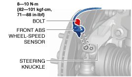
1. Remove the front ABS wheel-speed sensor from the steering knuckle.
am2zzw00007248
|
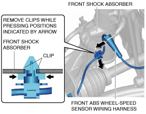
2. Remove the front ABS wheel-speed sensor wiring harness from the front shock absorber and set it aside so that it does not interfere with the servicing.
am2zzw00007249
|
3. Remove the front under cover No.2. (See FRONT UNDER COVER No.2 REMOVAL/INSTALLATION.)
4. Remove the splash shield. (See SPLASH SHIELD REMOVAL/INSTALLATION.)
5. Drain the manual transaxle oil or ATF. (See MANUAL TRANSAXLE OIL REPLACEMENT [F65M-R].) (See MANUAL TRANSAXLE OIL REPLACEMENT [F66M-R].) (See AUTOMATIC TRANSAXLE FLUID (ATF) REPLACEMENT [CW6A-EL].) (See AUTOMATIC TRANSAXLE FLUID (ATF) REPLACEMENT [EW6A-EL].)
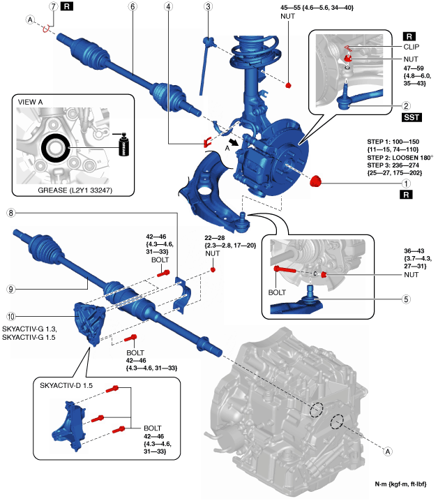
6. Remove in the order indicated in the table.
7. Install in the reverse order of removal.
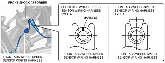
8. Install the front ABS wheel-speed sensor wiring harness as shown in the figure.
am2zzw00007231
|
9. After installation, add the specified manual transaxle oil or ATF. (See MANUAL TRANSAXLE OIL REPLACEMENT [F65M-R].) (See MANUAL TRANSAXLE OIL REPLACEMENT [F66M-R].) (See AUTOMATIC TRANSAXLE FLUID (ATF) REPLACEMENT [CW6A-EL].) (See AUTOMATIC TRANSAXLE FLUID (ATF) REPLACEMENT [EW6A-EL].)
am2zzw00007286
|
|
1
|
Locknut
(See Locknut Removal Note.)
(See Locknut Installation Note.)
|
|
2
|
Tie-rod end
(See TIE-ROD END REPLACEMENT.)
|
|
3
|
Stabilizer control link
|
|
4
|
Brake hose clip
|
|
5
|
Front lower arm ball joint
|
|
6
|
Front drive shaft (LH)
|
|
7
|
Front drive shaft clip
|
|
8
|
Bracket No.2
|
|
9
|
Front drive shaft (RH)
|
|
10
|
Bracket No.1
|
Locknut Removal Note
1. Remove the locknut with the brake pedal depressed.
Front Drive Shaft Removal Note [SKYACTIV-G 1.3, SKYACTIV-G 1.5]
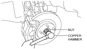
1. Install a spare nut onto the drive shaft.
2. Tap the nut with a copper hammer and separate the drive shaft from the axle.
am2zzw00007251
|
3. Separate the drive shaft from the wheel hub.
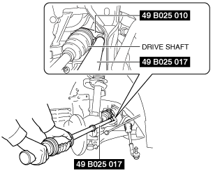
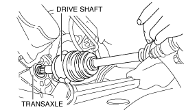
4. Perform the following procedures to separate the drive shaft (LH) from the transaxle.
am2zzw00007252
|
5. Remove the drive shaft.
Front Drive Shaft Removal Note [SKYACTIV-D 1.5]
1. Install a spare nut onto the drive shaft.
2. Tap the nut with a copper hammer and separate the drive shaft from the axle.
am2zzw00007251
|
3. Separate the drive shaft from the wheel hub.
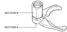
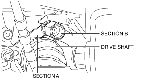
4. Perform the following procedures to separate the drive shaft (LH) from the transaxle.
am2zzw00007652
|
am2zzw00007653
|
am2zzw00007253
|
5. Remove the drive shaft.
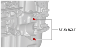
Bracket, Front Drive Shaft (RH) Installation Note
1. Tighten the bracket No.1 stud bolts.
am2zzw00007254
|
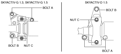
2. Temporarily tighten the bolts A and B.
am2zzw00007255
|
3. Tighten the bolts A, then tighten the bolt B to the specified torque.
4. Apply transaxle oil or ATF to the oil seal lip.
5. Insert the drive shaft into the transaxle until the drive shaft bearing contacts the bracket stopper.
6. Temporarily tighten the nuts C, then tighten the nuts C to the specified torque.
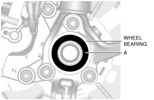
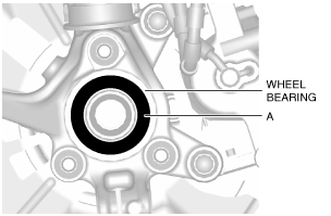
7. Apply grease (L2Y1 33247) to the wheel bearing inner race and drive shaft contact surface (Area A in figure).
am2zzw00007256
|
8. Insert the drive shaft into the wheel hub.
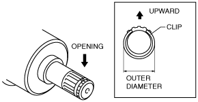
Front Drive Shaft Clip Installation Note
1. Install a new clip to the clip groove at the end of the front drive shaft with the clip opening facing upward.
am2zzw00007257
|
2. Verify that the outer diameter of the clip is within the specification.
Specification
|
Engine type |
Outer diameter |
|---|---|
|
SKYACTIV-G 1.3, SKYACTIV-G 1.5
|
Less than 28.0 mm {1.10 in}
|
|
SKYACTIV-D 1.5 (MTX)
|
Less than 28.0 mm {1.10 in}
|
|
SKYACTIV-D 1.5 (ATX)
|
Less than 34.0 mm {1.34 in}
|
Front Drive Shaft (LH) Installation Note
1. Apply transaxle oil or ATF to the oil seal lip.
2. Apply grease (L2Y1 33247) to the wheel bearing inner race and drive shaft contact surface (Area A in figure).
am2zzw00007258
|
3. Insert the drive shaft into the wheel hub.
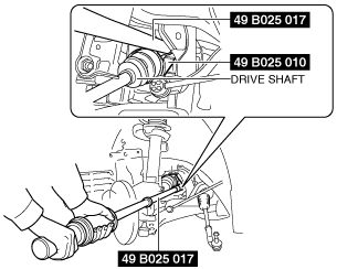
4. Install the drive shaft to the transaxle.
am2zzw00007259
|
5. After installation, pull the transaxle side outer ring forward to confirm that the drive shaft is securely held by the clip.
Locknut Installation Note
1. If dust or grease is on the drive shaft thread area, wipe it off with a cloth.
2. Tighten the locknut using the following procedure and with the brake pedal depressed.