BRAKE FLUID AIR BLEEDING
id041100815300
Rear Brake (Drum)
-
Caution
-
• Brake fluid will damage painted surfaces. Be careful not to spill any on painted surfaces. In addition, if there is any brake fluid on the wiring harness, the wire insulation may corrode causing a malfunction such as a short circuit. If brake fluid gets on a painted surface or wiring harness, wash and flush it off completely with water immediately.
-
Note
-
• Keep the fluid level in the brake fluid reserve tank at 3/4 full or more during the air bleeding.
• Begin air bleeding with the wheel cylinder that is furthest from the master cylinder.
-
Brake fluid type [Rear brake (drum)]
-
SKYACTIV-G 1.3 or SKYACTIV-G 1.5: SAE J1703 or FMVSS116 DOT-3 or DOT-4
SKYACTIV-D 1.5: SAE J1703 or FMVSS116 DOT-4
1. Remove the cap from the brake fluid reserve tank and add brake fluid.
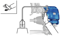
2. Remove the bleeder cap on the brake caliper/wheel cylinder, and attach a vinyl tube to the bleeder screw.
3. Place the other end of the vinyl tube in a clear container and fill the container with fluid during air bleeding.
4. Working with two people, one should pump the brake pedal several times and depress and hold the pedal down.
5. While one technician depresses the brake pedal and another technician loosens the bleeder screw, drain any fluid containing air bubbles, and then retighten the bleeder screw.
-
Tightening torque
-
Front: 6.9—9.8 N·m {71—99 kgf·cm, 62—86 in·lbf}
Rear: 6.9—8.8 N·m {71—89 kgf·cm, 62—77 in·lbf}
6. Repeat Steps 4 and 5 until no air bubbles are seen.
7. Perform air bleeding as described in the above procedures for all brake calipers/wheel cylinders.
8. Clean the brake calipers/wheel cylinders.
9. After air bleeding, inspect the following:
-
• Brake operation
• Fluid leakage
• Fluid level
Rear Brake (Disc)
-
Caution
-
• Brake fluid will damage painted surfaces. Be careful not to spill any on painted surfaces. In addition, if there is any brake fluid on the wiring harness, the wire insulation may corrode causing a malfunction such as a short circuit. If brake fluid gets on a painted surface or wiring harness, wash and flush it off completely with water immediately.
-
Note
-
• Keep the fluid level in the brake fluid reserve tank at 3/4 full or more during the air bleeding.
• Begin air bleeding with the brake caliper that is furthest from the master cylinder.
-
Brake fluid type [Rear brake (disc)]
-
SAE J1703 or FMVSS116 DOT-3 or DOT-4
1. Remove the cap from the brake fluid reserve tank and add brake fluid.
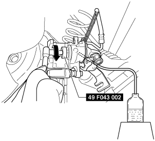
2. Remove the bleeder cap on the brake caliper, and attach a vinyl tube to the bleeder screw.
3. Place the other end of the vinyl tube in a clear container and fill the container with fluid during air bleeding.
4. Working with two people, one should pump the brake pedal several times and depress and hold the pedal down.
5. While one technician depresses the brake pedal and another technician loosens the bleeder screw, drain any fluid containing air bubbles, and then retighten the bleeder screw.
-
Tightening torque
-
6.9—9.8 N·m {71—99 kgf·cm, 62—86 in·lbf}
6. Repeat Steps 4 and 5 until no air bubbles are seen.
7. Perform air bleeding as described in the above procedures for all brake calipers.
8. After performing normal air bleeding, perform air bleeding again for the right and left rear calipers using the following procedure:
- (1) Remove the center console tray. (See CENTER CONSOLE TRAY REMOVAL/INSTALLATION.)
- (2) Loosen the adjusting nut. (See PARKING BRAKE LEVER ADJUSTMENT.)
- (3) Remove the clip and disconnect the rear parking brake cable from the rear caliper. (See REAR PARKING BRAKE CABLE REMOVAL/INSTALLATION [REAR BRAKE (DISC)].)
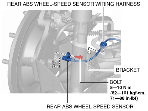
- (4) Remove the rear ABS wheel-speed sensor from the wheel hub component.
-
- (5) Remove the rear ABS wheel-speed sensor wiring harness from the bracket and set it aside.
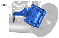
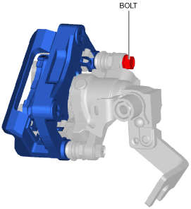
- (6) Loosen the caliper installation bolt.
-
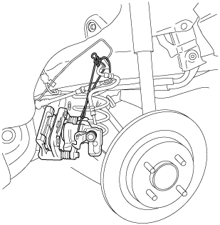
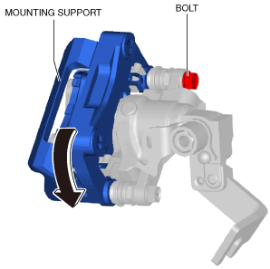
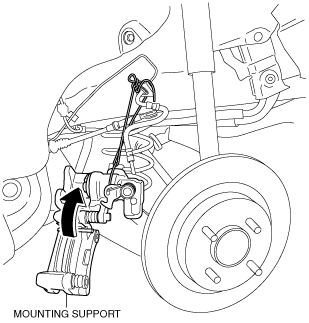
- (7) Remove the mounting support bolt and suspend it with a cable. (See REAR BRAKE (DISC) REMOVAL/INSTALLATION.)
-
- (8) Remove the caliper bolt and move the mounting support.
-
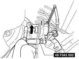
- (9) Slowly rotate the piston counterclockwise approx. 180° using the SST.
-
- (10) Loosen the bleeder screw.
- (11) Rotate the piston clockwise slowly using the SST and push the piston inwards completely to bleed air.
-
- (12) Tighten the bleeder screw.
-
-
Tightening torque
-
6.9—9.8 N·m {71—99 kgf·cm, 62—86 in·lbf}
- (13) Repeat the procedure from Steps 8 to 11 until no air bubbles are seen.
- (14) Remove the disc pads and shim from the mounting support.
- (15) Clean the area where the double-sided adhesive tape of the caliper, piston and shim is to be applied.
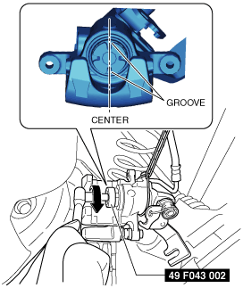
- (16) Rotate the piston clockwise slowly using the SST and push the piston completely until the piston grooves are in the position shown in the figure.
-
- (17) Peel off the paper backing of the double-sided adhesive tape from the inner shim on the disc pad side.
- (18) Install the new shim to the disc pads.
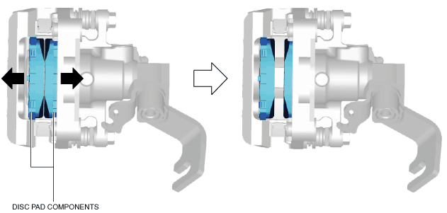
- (19) Install the disc pad components to the mounting support.
- (20) Move the disc pad components in the direction of the arrows shown in the figure.
-
- (21) Peel off the backing of the double-sided adhesive tape from the shim.
- (22) Move the mounting support in the direction of the arrow shown in the figure.
-
-
Caution
-
• If the double-sided adhesive tape affixed to the shim contacts the caliper and piston, the tape's adhesive surface will roughen causing disc pad wear which may become a source of noise when the mounting support moves. When moving the mounting support be careful not to allow the double-sided adhesive tape on the shim to contact the caliper and piston.
- (23) Temporarily install the caliper installation bolt.
-
- (24) Move the disc pad components in the direction of the arrows shown in the figure and lightly affix the double-sided adhesive tape on the shim to the piston and caliper.
-
- (25) Install the mounting support. (See REAR BRAKE (DISC) REMOVAL/INSTALLATION.)
- (26) Tighten the caliper installation bolt. (See REAR BRAKE (DISC) REMOVAL/INSTALLATION.)
- (27) Install the rear parking brake cable. (See REAR PARKING BRAKE CABLE REMOVAL/INSTALLATION [REAR BRAKE (DISC)].)
- (28) Inspect the parking brake lever stroke. (See PARKING BRAKE LEVER INSPECTION.)
- (29) Pump the brake pedal a few times to apply pressure to attach the double-sided adhesive tape on the shim to the caliper and piston.
- (30) Inspect the following:
-
-
― The disc pad projection is securely installed to the piston groove
― Brake drag
- (31) Repeat the following procedure three times:
-
- 1) Working with two people, one should pump the brake pedal several times and depress and hold the pedal down.
- 2) While the brake pedal is depressed, the other person should loosen the bleeder screw, drain out any fluid containing air bubbles, and tighten the bleeder screw.
-
-
Tightening torque
-
6.9—9.8 N·m {71—99 kgf·cm, 62—86 in·lbf}
- 3) Pump the brake pedal ten times.
- 4) Pull the parking brake lever ten times.
- 5) Repeatedly loosen and tighten the bleeder screw five times with the brake pedal depressed.
-
-
Tightening torque
-
6.9—9.8 N·m {71—99 kgf·cm, 62—86 in·lbf}
9. Clean the brake calipers.
10. After air bleeding, inspect the following:
-
• Brake operation
• Fluid leakage
• Fluid level