 |
am2zzw00008169
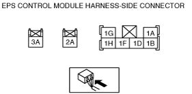
EPS CONTROL MODULE INSPECTION
id061300802400
1. Remove the following parts:
2. Partially peel back the seaming welt.
3. Remove the driver-side lower panel. (See DRIVER-SIDE LOWER PANEL REMOVAL/INSTALLATION.)
4. Measure the terminal voltage of the EPS control module using a tester.
Terminal Voltage Table (Reference)
am2zzw00008169
|
|
Terminal |
Signal name |
Connected to |
Measured item |
Measured terminal (measurement condition) |
Specification |
Inspection item(s) |
|---|---|---|---|---|---|---|
|
1A
|
—
|
—
|
—
|
—
|
—
|
—
|
|
1B
|
—
|
—
|
—
|
—
|
—
|
—
|
|
1D
|
—
|
—
|
—
|
—
|
—
|
—
|
|
1F
|
Ignition power supply
|
IG1 relay
|
Voltage
|
Ignition ON (engine off)
|
B+
|
• Wiring harness (EPS control module terminal 1F—IG1 relay)
|
|
Ignition off
|
1.0 V or less
|
|||||
|
1G
|
CAN_H
|
CAN related module
|
Because this terminal is for communication, determination using terminal voltage inspection is not possible. Perform the inspection using the DTC inspection.
|
|||
|
1H
|
CAN_L
|
CAN related module
|
Because this terminal is for communication, determination using terminal voltage inspection is not possible. Perform the inspection using the DTC inspection.
|
|||
|
2A
|
Ground
|
Ground point
|
Voltage
|
Under any condition
|
1.0 V or less
|
• Wiring harness (EPS control module terminal 2A—ground point)
|
|
3A
|
Battery power supply
|
Battery
|
Voltage
|
Under any condition
|
B+
|
• Wiring harness (EPS control module terminal 3A—battery)
|