|
1
|
VERIFY BCM DTCs AGAIN
• Clear the DTC for the BCM using the M-MDS.
• Lock/unlock all the doors by operating the driver’s door lock knob.
• Retrieve the BCM DTCs using the M-MDS with the front door lock-link switch (driver's side) unlocked.
• Is the same DTC displayed?
|
Yes
|
Go to the next step.
|
|
No
|
Go to Step 9.
|
|
2
|
VERIFY OTHER BCM DTCs AGAIN
• Clear the DTC for the BCM using the M-MDS.
• Retrieve the BCM DTCs using the M-MDS with the front door lock-link switch (driver's side) locked.
• Is DTC B126A:11 or B126A:13 displayed?
|
Yes
|
Repair or replace the malfunctioning part according to the applicable DTC troubleshooting.
|
|
No
|
Go to the next step.
|
|
3
|
INSPECT FRONT DOOR LATCH AND LOCK ACTUATOR (DRIVER'S SIDE) CONNECTOR CONDITION
• Switch the ignition off.
• Disconnect the negative battery cable.
• Disconnect the front door latch and lock actuator (driver's side) connector.
• Inspect the connector engagement and connection condition and inspect the terminals for damage, deformation, corrosion, or disconnection.
• Is the connector normal?
|
Yes
|
Go to the next step.
|
|
No
|
Repair or replace the connector, then go to Step 8.
|
|
4
|
INSPECT FRONT DOOR LOCK-LINK SWITCH (DRIVER'S SIDE) GROUND CIRCUIT FOR OPEN CIRCUIT
• Verify that the front door latch and lock actuator (driver's side) connector is disconnected.
• Inspect for continuity between the following terminal (wiring harness-side) and body ground:
-
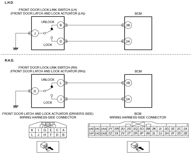
― Front door latch and lock actuator (LH) terminal J (L.H.D.)
― Front door latch and lock actuator (RH) terminal D (R.H.D.)
• Is there continuity?
|
Yes
|
Go to the next step.
|
|
No
|
Refer to the wiring diagram and verify whether or not there is a common connector between the following terminals:
• Front door latch and lock actuator (LH) terminal J—Body ground (L.H.D.)
• Front door latch and lock actuator (RH) terminal D—Body ground (R.H.D.)
If there is a common connector:
• Determine the malfunctioning part by inspecting the common connector and the terminal for corrosion, damage, or pin disconnection, and the common wiring harness for an open circuit.
• Repair or replace the malfunctioning part.
If there is no common connector:
• Repair or replace the wiring harness which has an open circuit.
Go to Step 8.
|
|
5
|
INSPECT FRONT DOOR LOCK-LINK SWITCH (DRIVER'S SIDE)
• Inspect the front door lock-link switch (driver's side).
• Is the front door lock-link switch (driver's side) normal?
|
Yes
|
Go to the next step.
|
|
No
|
Replace the front door latch and lock actuator (driver's side), then go to Step 8.
|
|
6
|
INSPECT BCM CONNECTOR CONDITION
• Disconnect the BCM connector.
• Inspect the connector engagement and connection condition and inspect the terminals for damage, deformation, corrosion, or disconnection.
• Is the connector normal?
|
Yes
|
Go to the next step.
|
|
No
|
Repair or replace the connector, then go to Step 8.
|
|
7
|
INSPECT FRONT DOOR LOCK-LINK SWITCH (DRIVER'S SIDE) UNLOCK CIRCUIT FOR OPEN CIRCUIT
• Verify that the front door latch and lock actuator (driver's side) and BCM connectors are disconnected.
• Inspect for continuity between the following terminals (wiring harness-side):
-
― Front door latch and lock actuator (LH) terminal B—BCM terminal 2B (L.H.D.)
― Front door latch and lock actuator (RH) terminal L—BCM terminal 2B (R.H.D.)
• Is there continuity?
|
Yes
|
Go to the next step.
|
|
No
|
Refer to the wiring diagram and verify whether or not there is a common connector between the following terminals:
• Front door latch and lock actuator (LH) terminal B—BCM terminal 2B (L.H.D.)
• Front door latch and lock actuator (RH) terminal L—BCM terminal 2B (R.H.D.)
If there is a common connector:
• Determine the malfunctioning part by inspecting the common connector and the terminal for corrosion, damage, or pin disconnection, and the common wiring harness for an open circuit.
• Repair or replace the malfunctioning part.
If there is no common connector:
• Repair or replace the wiring harness which has an open circuit.
Go to the next step.
|
|
8
|
VERIFY THAT REPAIRS HAVE BEEN COMPLETED
• Always reconnect all disconnected connectors.
• Connect the negative battery cable.
• Clear the DTC for the BCM using the M-MDS.
• Lock/unlock all the doors by operating the driver’s door lock knob.
• Retrieve the BCM DTCs using the M-MDS with the front door lock-link switch (driver's side) unlocked.
• Is the same DTC displayed?
|
Yes
|
Repeat the inspection from Step 1.
• If the malfunction recurs, replace the BCM.
Go to the next step.
|
|
No
|
Go to the next step.
|
|
9
|
VERIFY IF OTHER DTCs DISPLAYED
• Are any other DTCs displayed?
|
Yes
|
Repair or replace the malfunctioning part according to the applicable DTC troubleshooting.
|
|
No
|
DTC troubleshooting completed.
|