 |
am2zzw00012439
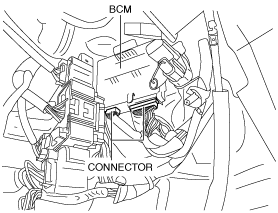
BODY CONTROL MODULE (BCM) REMOVAL/INSTALLATION
id094000003800
L.H.D.
1. If the BCM is replaced and the auto configuration is not performed, perform the configuration using the M-MDS. (See BODY CONTROL MODULE (BCM) CONFIGURATION (USING READ/WRITE FUNCTION).)
2. Disconnect the negative battery cable. (See NEGATIVE BATTERY CABLE DISCONNECTION/CONNECTION.)
3. Remove the following parts:
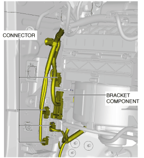
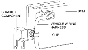
4. Remove the vehicle wiring harness clip from the bracket component.
am2zzw00012439
|
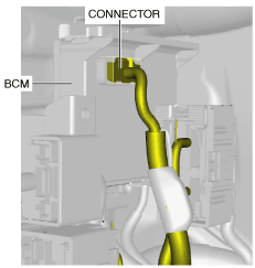
5. Disconnect the connector.
am2zzw00007477
|
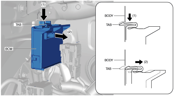
6. While pressing the BCM tab in the direction of arrow (1) shown in the figure, pull it in the direction of arrow (2) to detach the tab from the body.
am2zzw00008184
|
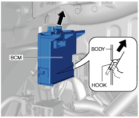
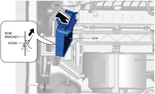
7. Pull the BCM in the direction of the arrow shown in the figure and detach the hook from the body.
am2zzw00008185
|
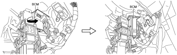
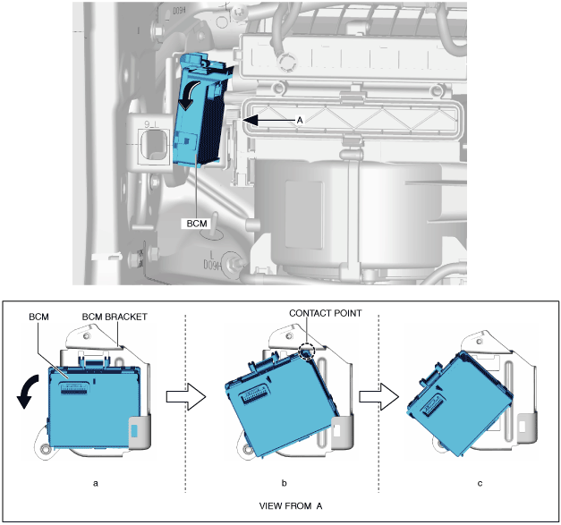
8. Rotate the BCM in the direction of the arrow shown in the figure and remove it.
am2zzw00007479
|
9. Disconnect the connectors.
am2zzw00007480
|
10. Remove the BCM.
11. Install in the reverse order of removal.
12. If the BCM is replaced and the auto configuration is performed, perform the auto configuration using the following procedure.
R.H.D.
1. If the BCM is replaced and the auto configuration is not performed, perform the configuration using the M-MDS. (See BODY CONTROL MODULE (BCM) CONFIGURATION (USING READ/WRITE FUNCTION).)
2. Disconnect the negative battery cable. (See NEGATIVE BATTERY CABLE DISCONNECTION/CONNECTION.)
3. Remove the following parts:
4. Disconnect the connectors.
am2zzw00007481
|
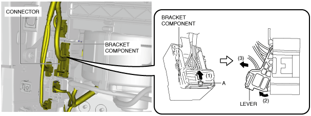
5. While detaching the tab by pressing part A in the direction of arrow (1) shown in the figure, move the lever in the direction of arrow (2) and disconnect the connector in the direction of arrow (3).
adejjw00010018
|
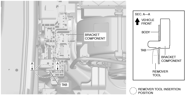
6. Remove the vehicle wiring harness clip from the bracket component.
am2zzw00012439
|
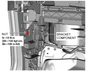
7. Remove the nut.
am2zzw00007482
|
8. Insert the remover tool into the position shown in the figure.
am2zzw00007483
|
9. Detach the tab from the body using the remover tool and remove the bracket component from the body.
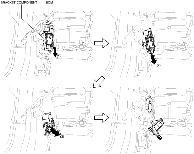
10. Move the bracket component in the order of the arrows shown in the figure and set it aside so that it does not interfere with the servicing.
am2zzw00013044
|
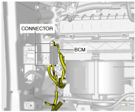
11. Disconnect the connectors.
am2zzw00007485
|
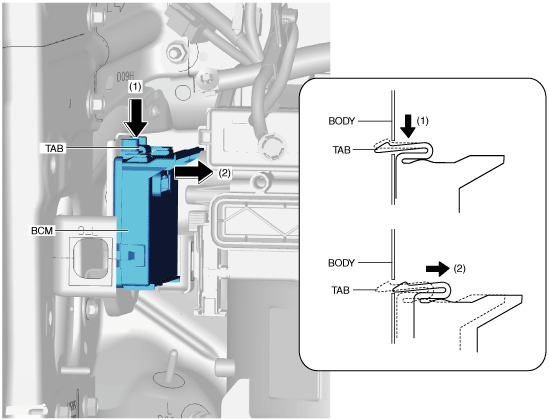
12. While pressing the BCM tab in the direction of arrow (1) shown in the figure, pull it in the direction of arrow (2) to detach the tab from the body.
am2zzw00007478
|
13. Move the BCM in the direction of the arrow shown in the figure.
am2zzw00013045
|
14. Move the BCM in the direction of the arrow shown in the figure and remove it while pulling out the hook.
am2zzw00013046
|
15. Install in the reverse order of removal.
16. If the BCM is replaced and the auto configuration is performed, perform the auto configuration using the following procedure.