|
1
|
INSPECT ELECTRICAL SUPPLY UNIT (ESU) CONNECTOR CONDITION
• Switch the ignition off.
• Disconnect the negative battery cable.
• Disconnect the electrical supply unit (ESU) connector.
• Inspect the connector engagement and connection condition and inspect the terminals for damage, deformation, corrosion, or disconnection.
• Is the connector normal?
|
Yes
|
Without i-ELOOP:
• Go to the next step.
With i-ELOOP:
• Go to Step 3.
|
|
No
|
Repair or replace the connector, then go to Step 9.
|
|
2
|
VERIFY ELECTRICAL SUPPLY UNIT (ESU) POWER SUPPLY VOLTAGE
• Connect the negative battery cable.
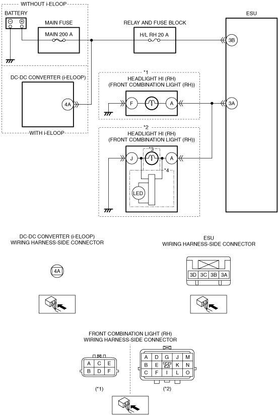
• Measure the voltage at the electrical supply unit (ESU) terminal 3B (wiring harness-side).
• Is the voltage B+?
|
Yes
|
With front combination light (bulb type):
• Go to Step 4.
With front combination light (LED type):
• Go to Step 5.
|
|
No
|
Inspect the H/L RH 20 A fuse and MAIN 200 A fuse.
• If the fuse is blown:
-
― Refer to the wiring diagram and verify whether or not there is a common connector between MAIN 200 A fuse and electrical supply unit (ESU) terminal 3B.
If there is a common connector:
-
• Determine the malfunctioning part by inspecting the common connector and the terminal for corrosion, damage, or pin disconnection, and the common wiring harness for a short to ground.
• Repair or replace the malfunctioning part.
If there is no common connector:
-
• Repair or replace the wiring harness which has a short to ground.
• Replace the fuse.
• If the fuse is damaged:
-
― Replace the fuse.
• If the fuse is normal:
-
― Refer to the wiring diagram and verify whether or not there is a common connector between battery positive terminal and electrical supply unit (ESU) terminal 3B.
If there is a common connector:
-
• Determine the malfunctioning part by inspecting the common connector and the terminal for corrosion, damage, or pin disconnection, and the common wiring harness for an open circuit.
• Repair or replace the malfunctioning part.
If there is no common connector:
-
• Repair or replace the wiring harness which has an open circuit.
Go to Step 9.
|
|
3
|
VERIFY ELECTRICAL SUPPLY UNIT (ESU) POWER SUPPLY VOLTAGE
• Connect the negative battery cable.
• Measure the voltage at the electrical supply unit (ESU) terminal 3B (wiring harness-side).
• Is the voltage B+?
|
Yes
|
With front combination light (bulb type):
• Go to the next step.
With front combination light (LED type):
• Go to Step 5.
|
|
No
|
Disconnect the service plug.
Inspect the H/L RH 20 A fuse.
• If the fuse is blown:
-
― Refer to the wiring diagram and verify whether or not there is a common connector between H/L RH 20 A fuse and electrical supply unit (ESU) terminal 3B.
If there is a common connector:
-
• Determine the malfunctioning location by inspecting the common connector and terminals for corrosion, damage, or disconnection and by inspecting the DC-DC converter (i-ELOOP) terminal 4A-related wiring harness for a short to ground.
• Repair or replace the malfunctioning part.
If there is no common connector:
-
• Repair or replace the wiring harness which is shorted to ground, or the DC-DC converter (i-ELOOP) terminal 4A-related wiring harness.
• Replace the fuse.
• If the fuse is damaged:
-
― Replace the fuse.
• If the fuse is normal:
-
― Refer to the wiring diagram and verify whether or not there is a common connector between DC-DC converter (i-ELOOP) terminal 4A and electrical supply unit (ESU) terminal 3B.
If there is a common connector:
-
• Determine the malfunctioning part by inspecting the common connector and the terminal for corrosion, damage, or pin disconnection, and the common wiring harness for an open circuit.
• Repair or replace the malfunctioning part.
If there is no common connector:
-
• Repair or replace the wiring harness which has an open circuit.
Connect the service plug, then go to Step 9.
|
|
4
|
VISUALLY INSPECT HEADLIGHT HI/LO BULB (RH)
• Visually inspect the headlight HI/LO bulb (RH).
• Is the headlight HI/LO bulb (RH) normal?
|
Yes
|
Go to the next step.
|
|
No
|
Replace the headlight HI/LO bulb (RH), then go to Step 9.
|
|
5
|
INSPECT FRONT COMBINATION LIGHT (RH) CONNECTOR CONDITION
• Switch the ignition off.
• Disconnect the negative battery cable.
• Disconnect the front combination light (RH) connector.
• Inspect the connector engagement and connection condition and inspect the terminals for damage, deformation, corrosion, or disconnection.
• Is the connector normal?
|
Yes
|
Go to the next step.
|
|
No
|
Repair or replace the connector, then go to Step 9.
|
|
6
|
INSPECT HEADLIGHT HI (RH) GROUND CIRCUIT FOR OPEN CIRCUIT
• Verify that the front combination light (RH) connector is disconnected.
• Inspect for continuity between the following terminals (wiring harness-side) and body ground:
-
― Front combination light (RH) terminal F (With front combination light (bulb type) and without headlight manual leveling system)
― Front combination light (RH) terminal J (With front combination light (LED type) or headlight manual leveling system)
• Is there continuity?
|
Yes
|
Go to the next step.
|
|
No
|
Refer to the wiring diagram and verify whether or not there is a common connector between the following terminals:
• Front combination light (RH) terminal F—Body ground (With front combination light (bulb type) and without headlight manual leveling system)
• Front combination light (RH) terminal J—Body ground (With front combination light (LED type) or headlight manual leveling system)
If there is a common connector:
• Determine the malfunctioning part by inspecting the common connector and the terminal for corrosion, damage, or pin disconnection, and the common wiring harness for an open circuit.
• Repair or replace the malfunctioning part.
If there is no common connector:
• Repair or replace the wiring harness which has an open circuit.
Go to Step 9.
|
|
7
|
INSPECT HEADLIGHT HI (RH) CIRCUIT FOR OPEN CIRCUIT
• Verify that the front combination light (RH) and electrical supply unit (ESU) connectors are disconnected.
• Inspect the wiring harness for continuity between front combination light (RH) terminal A (wiring harness-side) and electrical supply unit (ESU) terminal 3A (wiring harness-side).
• Is there continuity?
|
Yes
|
With front combination light (bulb type):
• Go to Step 9.
With front combination light (LED type):
• Go to the next step.
|
|
No
|
Refer to the wiring diagram and verify whether or not there is a common connector between front combination light (RH) terminal A and electrical supply unit (ESU) terminal 3A.
If there is a common connector:
• Determine the malfunctioning part by inspecting the common connector and the terminal for corrosion, damage, or pin disconnection, and the common wiring harness for an open circuit.
• Repair or replace the malfunctioning part.
If there is no common connector:
• Repair or replace the wiring harness which has an open circuit.
Go to Step9.
|
|
8
|
VERIFY IF MALFUNCTIONING LOCATION IS FRONT COMBINATION LIGHT (RH) DEPENDING ON REPEATABILITY
• Always reconnect all disconnected connectors.
• Connect the negative battery cable.
• Clear the DTC for the electrical supply unit (ESU) using the M-MDS.
• Operate the light switch to the HEAD position and the dimmer switch to HI position.
• Retrieve the electrical supply unit (ESU) DTCs using the M-MDS.
• Is the same DTC displayed?
|
Yes
|
Replace the front combination light (RH), then go to the next step.
|
|
No
|
Go to Step 10.
|
|
9
|
VERIFY THAT REPAIRS HAVE BEEN COMPLETED
• Always reconnect all disconnected connectors.
• Connect the negative battery cable.
• Clear the DTC for the electrical supply unit (ESU) using the M-MDS.
• Operate the light switch to the HEAD position and the dimmer switch to HI position.
• Retrieve the electrical supply unit (ESU) DTCs using the M-MDS.
• Is the same DTC displayed?
|
Yes
|
Repeat the inspection from Step 1.
• If the malfunction recurs, replace the electrical supply unit (ESU).
Go to the next step.
|
|
No
|
Go to the next step.
|
|
10
|
VERIFY IF OTHER DTCs DISPLAYED
• Are any other DTCs displayed?
|
Yes
|
Repair or replace the malfunctioning part according to the applicable DTC troubleshooting.
|
|
No
|
DTC troubleshooting completed.
|