 |
am2zzw00008544
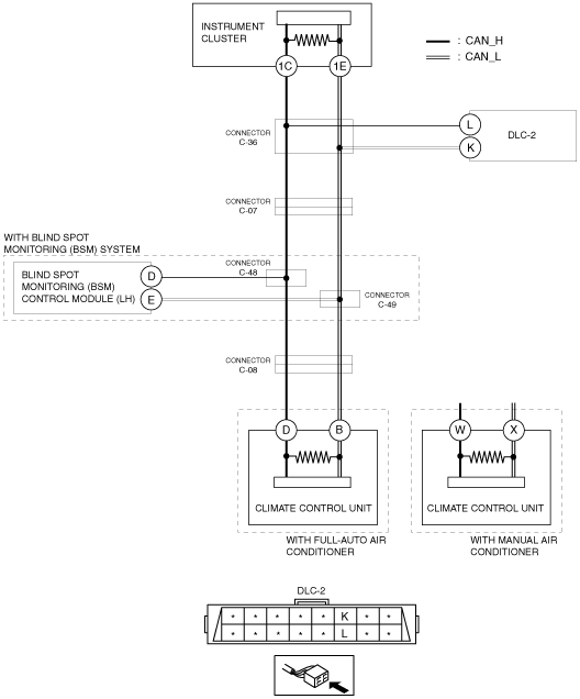
DETERMINING SHORT TO POWER SUPPLY LOCATION (MS-CAN) [SKYACTIV-G 1.5 (L.H.D.)]
id100219001000
System Wiring Diagram
am2zzw00008544
|
Determination procedure
|
Step |
Inspection |
Action |
|
|---|---|---|---|
|
1
|
INSPECT FOR SHORT TO POWER SUPPLY BETWEEN CONNECTOR C-36 AND INSTRUMENT CLUSTER
• Switch the ignition off.
• Disconnect the negative battery cable.
• Disconnect the connector C-36.
• Connect the negative battery cable.
• Switch the ignition ON (engine off).
• Measure the voltage at instrument cluster terminals 1C and 1E.
• Is the voltage between 1.5—3.5 V?
|
Yes
|
Go to Step 3.
|
|
No
|
Go to the next step.
|
||
|
2
|
INSPECT INSTRUMENT CLUSTER FOR SHORT TO POWER SUPPLY
• Switch the ignition off.
• Disconnect the negative battery cable.
• Disconnect the instrument cluster connector.
• Connect the connector C-36.
• Connect the negative battery cable.
• Switch the ignition ON (engine off).
• Measure the voltage at DLC-2 terminals L and K.
• Is the voltage between 1.5—3.5 V?
|
Yes
|
Replace the instrument cluster because there is a short to the power supply in the instrument cluster.
|
|
No
|
Repair or replace the wiring harness between the instrument cluster and connector C-36 because the wiring harness is shorted to the power supply.
|
||
|
3
|
INSPECT FOR SHORT TO POWER SUPPLY BETWEEN CONNECTORS C-36 AND DLC-2
• Measure the voltage at DLC-2 terminals L and K.
• Is the voltage 0 V?
|
Yes
|
Go to the next step.
|
|
No
|
Repair or replace the wiring harness between DLC-2 and connector C-36 because the wiring harness is shorted to the power supply.
|
||
|
4
|
INSPECT FOR SHORT TO POWER SUPPLY BETWEEN CONNECTOR C-36 AND CONNECTOR C-07
• Switch the ignition off.
• Disconnect the negative battery cable.
• Disconnect the connector C-07.
• Connect the connector C-36.
• Connect the negative battery cable.
• Switch the ignition ON (engine off).
• Measure the voltage at DLC-2 terminals L and K.
• Is the voltage between 1.5—3.5 V?
|
Yes
|
Go to the next step.
|
|
No
|
Repair or replace the wiring harness between connector C-36 and connector C-07 because the wiring harness is shorted to the power supply.
|
||
|
5
|
INSPECT FOR SHORT TO POWER SUPPLY BETWEEN CONNECTOR C-07 AND CONNECTORS C-48 AND C49
• Switch the ignition off.
• Disconnect the negative battery cable.
• Connect the connector C-07.
• Disconnect the connectors C-48 and C-49.
• Connect the negative battery cable.
• Switch the ignition ON (engine off).
• Measure the voltage at DLC-2 terminals L and K.
• Is the voltage between 1.5—3.5 V?
|
Yes
|
Go to the next step.
|
|
No
|
Repair or replace the wiring harness between connector C-07 and connectors C-48 and C-49 because the wiring harness is shorted to the power supply.
|
||
|
6
|
INSPECT FOR SHORT TO POWER SUPPLY BETWEEN BLIND SPOT MONITORING (BSM) CONTROL MODULE (LH) AND CONNECTORS C-48 AND C49
• Measure the voltage at blind spot monitoring (BSM) control module (LH) terminals D and E.
• Is the voltage between 1.5—3.5 V?
|
Yes
|
Go to Step 8.
|
|
No
|
Go to the next step.
|
||
|
7
|
INSPECT BLIND SPOT MONITORING (BSM) CONTROL MODULE (LH) FOR SHORT TO POWER SUPPLY
• Switch the ignition off.
• Disconnect the negative battery cable.
• Disconnect the blind spot monitoring (BSM) control module (LH) connector.
• Connect the connectors C-48 and C-49.
• Connect the negative battery cable.
• Switch the ignition ON (engine off).
• Measure the voltage at DLC-2 terminals L and K.
• Is the voltage between 1.5—3.5 V?
|
Yes
|
Replace the blind spot monitoring (BSM) control module (LH) because there is a short to power supply in the blind spot monitoring (BSM) control module (LH).
|
|
No
|
Repair or replace the wiring harness between the blind spot monitoring (BSM) control module (LH) and connectors C-48 and C-49 because the wiring harness is shorted to the power supply.
|
||
|
8
|
INSPECT FOR SHORT TO POWER SUPPLY BETWEEN CONNECTORS C-48 AND C-49 AND CONNECTOR C-08
• Switch the ignition off.
• Disconnect the negative battery cable.
• Connect the connectors C-48 and C-49.
• Disconnect the connector C-08.
• Connect the negative battery cable.
• Switch the ignition ON (engine off).
• Measure the voltage at DLC-2 terminals L and K.
• Is the voltage between 1.5—3.5 V?
|
Yes
|
Go to the next step.
|
|
No
|
Repair or replace the wiring harness between the connector C-08 and connectors C-48 and C-49 because the wiring harness is shorted to the power supply.
|
||
|
9
|
INSPECT CLIMATE CONTROL UNIT FOR SHORT TO POWER SUPPLY
• Switch the ignition off.
• Disconnect the negative battery cable.
• Disconnect the climate control unit connector.
• Connect the connector C-08.
• Connect the negative battery cable.
• Switch the ignition ON (engine off).
• Measure the voltage at DLC-2 terminals L and K.
• Is the voltage between 1.5—3.5 V?
|
Yes
|
Replace the climate control unit because there is a short to the power supply in the climate control unit.
|
|
No
|
Repair or replace the wiring harness between the climate control unit and connector C-08 because the wiring harness is shorted to the power supply.
|
||