PCM REMOVAL/INSTALLATION [SKYACTIV-G 1.3, SKYACTIV-G 1.5]
id0140q1802400
-
Caution
-
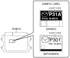
• There are two types of PCM settings. If the incorrect PCM is installed, it could cause interference with engine control.
• When replacing the PCM, verify the first four digits of the part number indicated on the PCM label before replacement, and replace the PCM with one having the same part number.
• If configuration and reprogramming is not performed when the PCM is replaced with a new one, the vehicle specification information and PCM software is not stored in the PCM and the system will not operate normally.
• When performing configuration and reprogramming, it is necessary to read the vehicle specification information from the PCM before replacing it. Connect the M-MDS to the vehicle and perform vehicle identification before removing the PCM. The vehicle specification information is temporarily stored in the M-MDS.
-
Note
-
• The PCM prior to replacement stores the vehicle specification information.
• A new PCM does not store any vehicle specification information.
• If the vehicle specification information PCM prior to replacement cannot be read, perform the configuration using As-Built data.
Without Set Bolt
1. Disconnect the negative battery cable. (See NEGATIVE BATTERY CABLE DISCONNECTION/CONNECTION.)
2. Remove the PCM together with the battery tray as a single unit. (See BATTERY REMOVAL/INSTALLATION [SKYACTIV-G 1.3, SKYACTIV-G 1.5].)
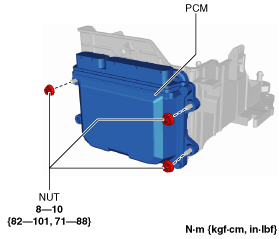
3. Remove the nuts.
4. Remove the PCM.
5. Install in the reverse order of removal.
6. When replacing the PCM on the vehicles, perform the following:
-
Note
-
-
With Set Bolt
1. Disconnect the negative battery cable. (See NEGATIVE BATTERY CABLE DISCONNECTION/CONNECTION.)
2. Remove the PCM together with the battery tray as a single unit. (See BATTERY REMOVAL/INSTALLATION [SKYACTIV-G 1.3, SKYACTIV-G 1.5].)
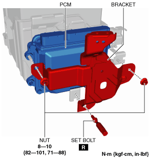
3. Remove the nuts and set bolt. (See Set bolt removal note.) (See Set bolt installation note.)
4. Remove the bracket.
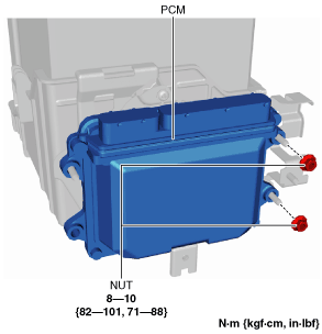
5. Remove the nuts.
6. Remove the PCM.
7. Install in the reverse order of removal.
8. When replacing the PCM on the vehicles, perform the following:
-
Note
-
-
Set bolt removal note
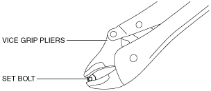
1. Remove the set bolt shown in the figure using a pair of vice grip pliers. (With set bolt)
-
Warning
-
• The vice grip pliers could slip on the conically-shaped set bolts and cause injury. Keep the set bolts wedged firmly in the vice grip pliers so that the pliers do not slip.
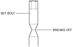
Set bolt installation note
1. Install a new set bolt and tighten it until the neck of the bolt breaks off.