 |
am2zzw00012386
BATTERY REMOVAL/INSTALLATION [SKYACTIV-G 1.3, SKYACTIV-G 1.5]
id0117008005q7
Operation After Replacing Battery (With i-stop)
|
Step |
Action |
|---|---|
|
1
|
Switch the ignition ON (engine off).
|
|
2
|
Shift the selector lever to the N position. (ATX)
Shift the shift lever to the neutral position. (MTX)
|
|
3
|
Perform the following work with the brake pedal depressed.
1. Depress the accelerator pedal for 5 s or more.
2. Verify that the charging system warning light and the master warning light flash.
3. Depress and release the accelerator pedal 3 times.
4. Verify that the charging system warning light illuminates and the master warning light turns off.
|
|
4
|
Switch the ignition off and disconnect the negative battery cable. (See NEGATIVE BATTERY CABLE DISCONNECTION/CONNECTION.)
|
|
5
|
Verifying battery condition initialization setting (i-stop setting). (See BATTERY CONDITION INITIALIZATION SETTING (i-stop SETTING).)
|
Operation After Replacing Battery (with i-ELOOP, without i-stop)
|
Step |
Action |
|---|---|
|
1
|
Switch the ignition ON (engine off).
|
|
2
|
Shift the selector lever to the N position.
|
|
3
|
Perform the following work with the brake pedal depressed.
1. Depress the accelerator pedal for 5 s or more.
2. Verify that the charging system warning light and the master warning light flash.
3. Depress and release the accelerator pedal 3 times.
4. Verify that the charging system warning light illuminates and the master warning light turns off.
|
|
4
|
Switch the ignition off and disconnect the negative battery cable. (See NEGATIVE BATTERY CABLE DISCONNECTION/CONNECTION.)
|
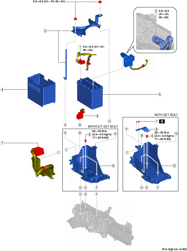
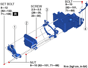
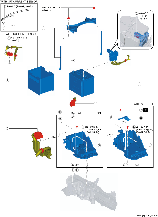
Battery Removal/Installation
1. Remove in the order indicated in the table.
2. Install in the reverse order of removal.
Without i-ELOOP
am2zzw00012386
|
|
1
|
Negative battery cable
|
|
2
|
Positive battery cable
|
|
3
|
Battery clamp
|
|
4
|
Battery box
|
|
5
|
Battery
|
|
6
|
Battery tray bolt
|
|
7
|
Set bolt (With set bolt)
(See Set bolt installation note.)
|
|
8
|
PCM cover (With set bolt)
|
|
9
|
PCM connector
|
|
10
|
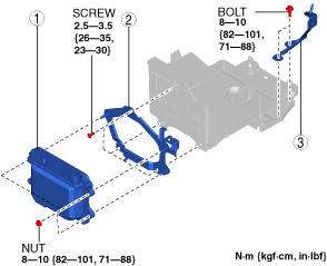
Battery tray and PCM component
|
With i-ELOOP
am2zzw00012387
|
|
1
|
Negative battery cable
|
|
2
|
Positive battery cable
|
|
3
|
Battery clamp
|
|
4
|
Battery box
|
|
5
|
Battery
|
|
6
|
Battery tray bolt
|
|
7
|
Set bolt (With set bolt)
(See Set bolt installation note.)
|
|
8
|
PCM cover (With set bolt)
|
|
9
|
PCM connector
|
|
10
|
Battery tray and PCM component
|
Battery tray and PCM component removal note
1. Remove the air cleaner, air hose and fresh air duct component. (See INTAKE-AIR SYSTEM REMOVAL/INSTALLATION [SKYACTIV-G 1.3, SKYACTIV-G 1.5].)
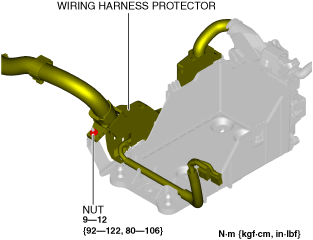
2. Remove the nut securing the wiring harness protector to the battery tray.
am2zzw00012388
|
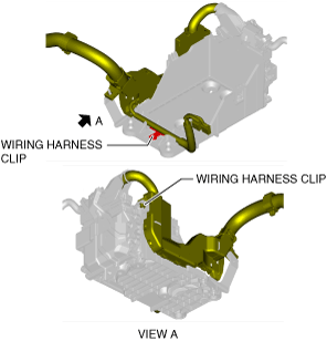
3. Release the wiring harness clips in the two locations shown in the figure.
am2zzw00012389
|
4. Disconnect the service plug. (with i-ELOOP) (See SERVICE PLUG DISCONNECTION/CONNECTION [i-ELOOP].)
5. DC-DC converter (i-ELOOP) (with i-ELOOP) (See DC-DC CONVERTER (i-ELOOP) REMOVAL/INSTALLATION [WITH i-ELOOP (SKYACTIV-G 1.3, SKYACTIV-G 1.5)].)
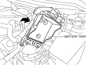
6. Pull out the battery tray and PCM component to the position shown in the figure to remove the set bolt. (With set bolt)
am2zzw00012390
|
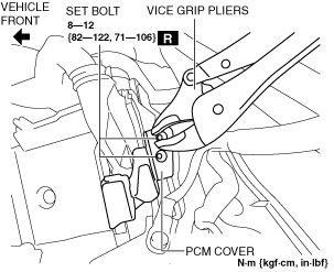
7. Remove the two set bolts shown in the figure using a pair of vice grip pliers. (With set bolt)
am2zzw00012391
|
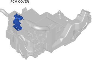
8. Remove the PCM cover shown in the figure. (with set bolt)
am2zzw00012392
|
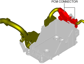
9. Disconnect the PCM connector shown in the figure.
am2zzw00012393
|
10. Remove the battery tray and PCM component.
11. When replacing the battery tray with a new one, perform the following procedure:
am2zzw00012394
|
am2zzw00012395
|
PCM connector connection note
am2zzw00012396
|
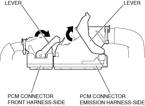
1. Set the PCM connector lever to the position shown in the figure.
am2zzw00012397
|
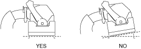
2. Align the PCM connector straight against the connection surface.
am3uuw00007477
|
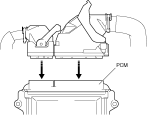
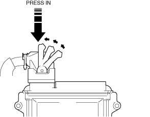
3. Insert the PCM connector straight and press it in until the lever moves up naturally. (Front harness-side connector)
am2zzw00012398
|
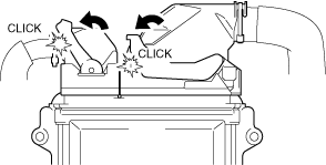
4. Press the PCM connector lever until a click sound is heard.
am2zzw00012399
|
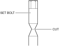
Set bolt installation note
1. Install a new set bolt and tighten it until the neck of the bolt is cut.
am2zzw00012400
|
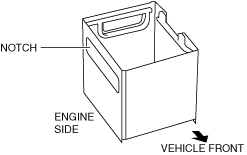
Battery box installation note
1. Install the battery box so that the side with the larger notch is pointed at the engine side.
am3zzw00015052
|
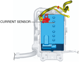
Negative battery cable connection note (with current sensor)
1. Connect the negative battery cable with the current sensor and the battery parallel to each other.
am2zzw00012401
|