|
1
|
INSPECT POWER SUPPLY CIRCUIT IN ABS HU/CM
• Switch the ignition OFF.
• Disconnect the ABS HU/CM connector.
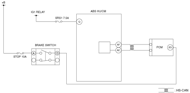
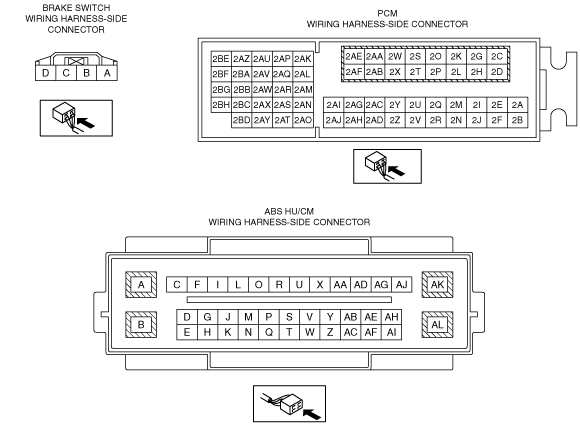
• Measure the voltage between ABS HU/CM terminal Q (wiring harness-side) and body ground.
• Is the voltage within followings?
-
― Ignition switch OFF: 1 V or less
― Ignition switch ON (engine off): B+
|
Yes
|
Go to the next step.
|
|
No
|
Refer to the wiring diagram and verify whether or not there is a common connector between IG1 relay and ABS HU/CM terminal Q.
If there is a common connector:
• Determine the malfunctioning part by inspecting the common connector and the terminal for corrosion, damage, or pin disconnection, and the common wiring harness for an open or short circuit.
• Repair or replace the malfunctioning part.
If there is no common connector:
• Repair or replace the wiring harness which has an open or short circuit.
Go to Step7.
|
|
2
|
INSPECT BRAKE SWITCH SIGNALCIRCUIT
• Measure the voltage between PCM terminal 2G (wiring harness-side)—body ground
• Is the voltage within followings?
-
― Brake pedal depressed: B+
― Brake pedal released: 1 V or less
|
Yes
|
Go to Step7.
|
|
No
|
• If it is B+ under any condition, then go to the next step.
• If it is 1 V or less under any condition, then go to Step 4
|
|
3
|
INSPECT BRAKE SWITCH SIGNALCIRCUIT FOR SHORT TO POWER SUPPLY
• Disconnect the brake switch connector.
• Measure the voltage between brake switch terminal D (wiring harness-side) and body ground.
• Is the voltage 1 V or less?
|
Yes
|
Go to Step5.
|
|
No
|
Refer to the wiring diagram and verify whether or not there is a common connector between brake switch terminal D and PCM terminal 2G.
If there is a common connector:
• Determine the malfunctioning part by inspecting the common connector and the terminal for corrosion, damage, or pin disconnection, and the common wiring harness for a short to power supply.
• Repair or replace the malfunctioning part.
If there is no common connector:
• Repair or replace the wiring harness which has a short to power supply.
Go to Step7.
|
|
4
|
INSPECT BRAKE SWITCH SIGNALCIRCUIT FOR OPEN CIRCUIT
• Disconnect the PCM connector.
• Inspect for continuity between brake switch terminal D (wiring harness-side) and PCM terminal 2G.
• Is there continuity?
|
Yes
|
Go to the next step.
|
|
No
|
Refer to the wiring diagram and verify whether or not there is a common connector between brake switch terminal D and PCM terminal 2G.
If there is a common connector:
• Determine the malfunctioning part by inspecting the common connector and the terminal for corrosion, damage, or pin disconnection, and the common wiring harness for an open circuit.
• Repair or replace the malfunctioning part.
If there is no common connector:
• Repair or replace the wiring harness which has an open circuit.
Go to Step7.
|
|
5
|
INSPECT BRAKE SWITCH
• Is the brake switch normal?
|
Yes
|
Go to the next step.
|
|
No
|
Replace the brake switch, then go to Step7.
|
|
6
|
VERIFY PCM DTC
• Using the M-MDS, perform the PCM DTC inspection.
• Are any DTCs present?
|
Yes
|
Go to applicable DTC inspection.
DTC troubleshooting completed, then go to the next step.
|
|
No
|
Go to the next step.
|
|
7
|
VERIFY DTC TROUBLESHOOTING COMPLETED
• Reconnect all disconnected connectors.
• Using the M-MDS, clear the DTC from the ABS HU/CM.
• Start the engine and drive the vehicle at 10 km/h {6.2 mph} or more.
• Using the M-MDS, perform the ABS HU/CM DTC inspection.
• Is the same DTC present?
|
Yes
|
Repeat the inspection from Step1.
If the malfunction recurs, replace the ABS HU/CM, then go to the next step.
|
|
No
|
Go to the next step.
|
|
8
|
VERIFY NO DTC IS PRESENT
• Are any DTCs present?
|
Yes
|
Go to applicable DTC inspection.
|
|
No
|
DTC troubleshooting completed.
|