 |
am2zzw00007447
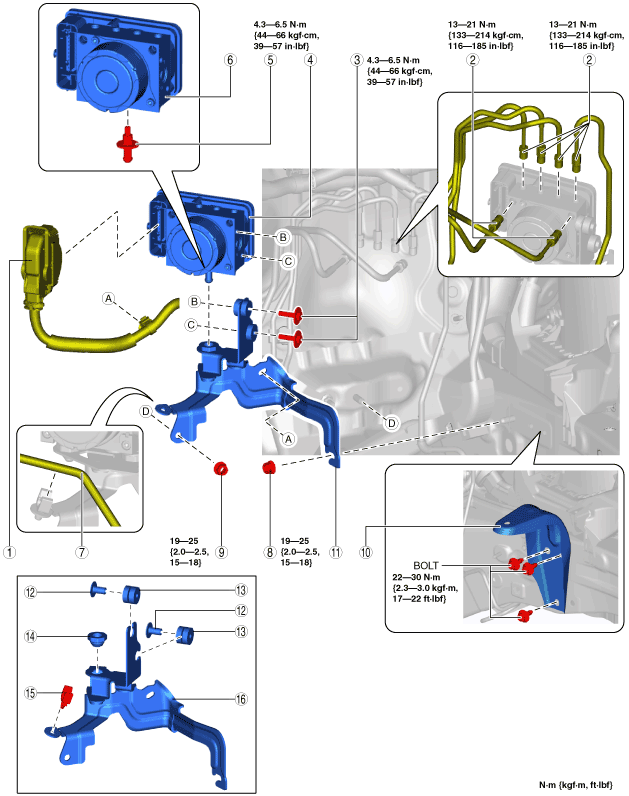
ABS HU/CM REMOVAL/INSTALLATION [R.H.D.]
id0413008014d2
1. Remove the following parts as a single unit. (See INTAKE-AIR SYSTEM REMOVAL/INSTALLATION [SKYACTIV-G 1.3, SKYACTIV-G 1.5].)
2. Remove the battery and battery tray. (See BATTERY REMOVAL/INSTALLATION [SKYACTIV-G 1.3, SKYACTIV-G 1.5].)
3. Remove in the order indicated in the table.
4. Install in the reverse order of removal.
5. After installation, add brake fluid, bleed the air, and inspect for fluid leakage. (See BRAKE FLUID AIR BLEEDING.)
6. Perform the ABS related parts sensor initialization procedure (only when replacing it with a new one). (See ABS RELATED PARTS SENSOR INITIALIZATION PROCEDURE.)
7. Clear the DTCs from the memory. (See CLEARING DTC [ABS HU/CM].)
am2zzw00007447
|
|
1
|
ABS HU/CM Connector
|
|
2
|
Brake pipe
(See Brake Pipe Removal Note.)
(See Brake Pipe Installation Note.)
|
|
3
|
Bolt
|
|
4
|
ABS HU/CM component
|
|
5
|
Bolt
|
|
6
|
ABS HU/CM
|
|
7
|
Clutch pipe (MTX)
|
|
8
|
Nut
|
|
9
|
Nut
|
|
10
|
Battery tray bracket
|
|
11
|
Bracket component
|
|
12
|
Spacer
|
|
13
|
Mount rubber
|
|
14
|
Mount rubber
|
|
15
|
Clip (MTX)
|
|
16
|
Bracket
|
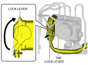
ABS HU/CM Connector Removal Note
1. Pull the lock lever up in the direction of the arrow while pressing the tab of the lock lever.
am2zzw00007448
|
2. Disconnect the ABS HU/CM connector.
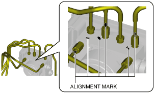
Brake Pipe Removal Note
1. Place an alignment marks on the brake pipe and ABS HU/CM.
am2zzw00007449
|
2. Apply protective tape to the connector to prevent brake fluid from entering.
3. Disconnect the brake pipes.
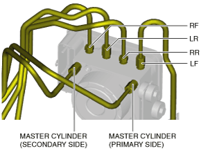
Brake Pipe Installation Note
1. Align the marks made before removal and install the brake pipe to the ABS HU/CM and brake pipe joint referring to the figure.
am2zzw00007451
|
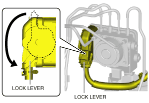
ABS HU/CM Connector Installation Note
1. Connect the connector and pull the lock lever down in the direction of the arrow.
am2zzw00007452
|
2. After connecting the connector, verify that the connector cover is completely pushed in.