 |
am2zzw00012796
BRAKE PEDAL REMOVAL/INSTALLATION [L.H.D.]
id041100801250
1. Remove the following parts as a single unit. (See INTAKE-AIR SYSTEM REMOVAL/INSTALLATION [SKYACTIV-G 1.3, SKYACTIV-G 1.5].) (See INTAKE-AIR SYSTEM REMOVAL/INSTALLATION [SKYACTIV-D 1.5].)
2. Remove the battery and battery tray. (See BATTERY REMOVAL/INSTALLATION [SKYACTIV-G 1.3, SKYACTIV-G 1.5].) (See BATTERY REMOVAL/INSTALLATION [SKYACTIV-D 1.5].)
3. For the SKYACTIV-D 1.5 (i-ELOOP) vehicle, perform the following procedure.
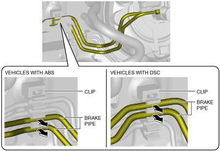
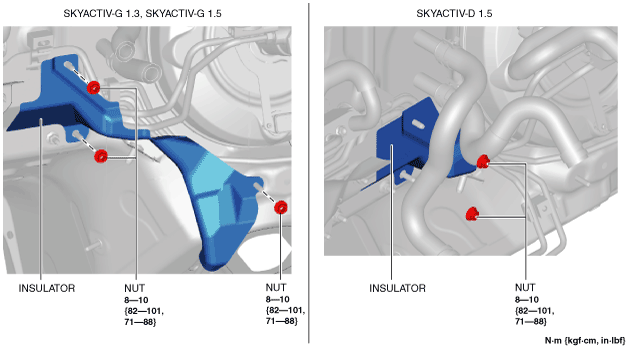
4. Remove the insulator.
am2zzw00012796
|
5. Detach the brake pipes from the clip.
am2zzw00007401
|
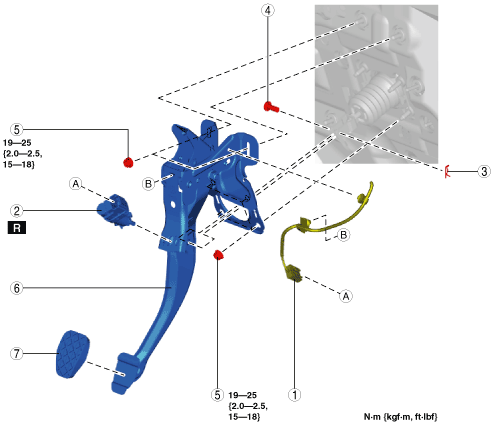
6. Remove in the order indicated in the table.
7. Install in the reverse order of removal.
am2zzw00007365
|
|
1
|
Brake switch connector and wiring harness
|
|
2
|
Brake switch
|
|
3
|
Snap pin
(See Snap Pin Installation Note.)
|
|
4
|
Clevis pin
|
|
5
|
Nut
(See Nut Installation Note.)
|
|
6
|
Brake pedal
(See Brake Pedal Removal Note.)
|
|
7
|
Pedal pad
|
Brake Pedal Removal Note
1. Move the power brake unit to the vehicle front where the power brake unit fork does not interfere with the brake pedal arm.
2. Remove the brake pedal.
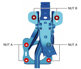
Nut Installation Note
1. Temporarily tighten the nuts A and B.
am2zzw00007366
|
2. Tighten the nuts A to the specified torque.
3. Tighten the nuts B to the specified torque.
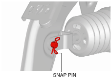
Snap Pin Installation Note
1. Install the snap pin as shown in the figure.
am2zzw00007367
|
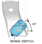
Brake Switch Installation Note
1. Inspect the brake pedal. (See BRAKE PEDAL INSPECTION.)
2. With the brake pedal fully released, insert a new brake switch into the installation hole on the brake pedal.
3. Secure the brake switch by turning it counterclockwise 45°.
am2zzw00007368
|