DTC
U3003:08
Battery power supply
U3003:16
U3003:17
DETECTION CONDITION
• U3003:08
-
― While the vehicle is traveling at a speed of 10km/h {6.2 mph} or more, a CAN signal error caused by low power supply voltage is detected
• U3003:16
-
― Low ignition voltage (7.9—9.6 V) is detected at the voltage monitor of the solenoid valve or motor monitor. (Except engine cranking condition)― Low ignition voltage (6.0—7.9 V) is detected at the voltage monitor of the solenoid valve or motor monitor― Low ignition voltage (below 6.0 V) is detected at the voltage monitor of the solenoid valve or motor monitor
• U3003:17
-
― High ignition voltage (17 V or more) is detected at the voltage monitor of the solenoid valve or motor monitor
FAIL-SAFE FUNCTION
Refer to DTC TABLE. (See DTC TABLE [DSC HU/CM].)
POSSIBLE CAUSE
Without i-ELOOP
• DTC is stored in PCM
• Battery malfunction
• Generator malfunction
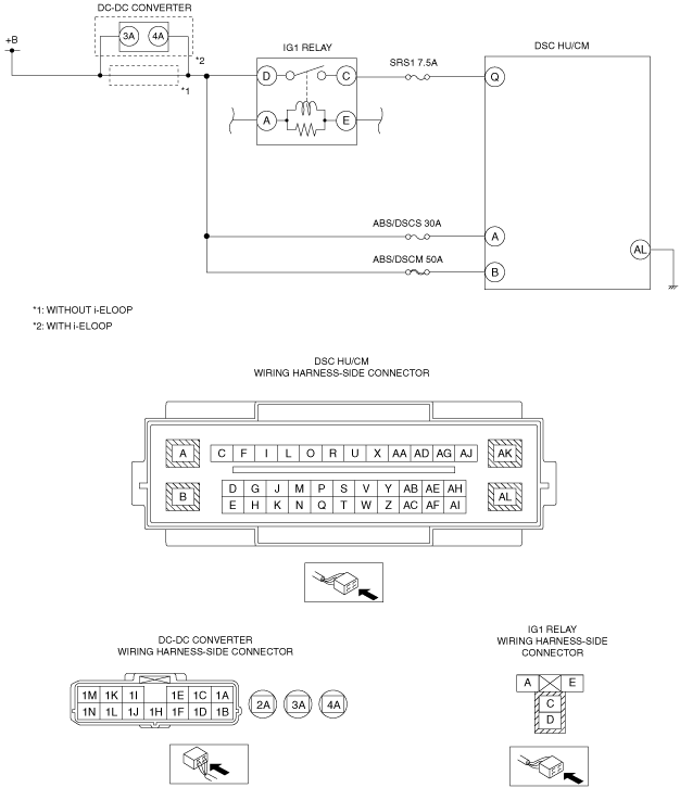
• Fuse (SRS1 7.5A, ABS/DSCS 30A, ABS/DSCM 50A) malfunction
• Open or short to GND circuit in wiring harness between battery and DSC HU/CM terminal Q
• Open or short to GND circuit in wiring harness between battery and DSC HU/CM terminal A
• Open or short to GND circuit in wiring harness between battery and DSC HU/CM terminal B
• Open circuit in wiring harness between DSC HU/CM terminal AL and body ground
• Poor connection at each connector
With i-ELOOP
• DTC is stored in PCM
• Battery malfunction
• DTC is stored in DC-DC converter (i-ELOOP)
• Fuse (SRS1 7.5A, ABS/DSCS 30A, ABS/DSCM 50A) malfunction
• Open or short to GND circuit in wiring harness between battery and DC-DC converter terminal 3A
• Open or short to GND circuit in wiring harness between DC-DC converter terminal 4A and DSC HU/CM terminal Q
• Open or short to GND circuit in wiring harness between DC-DC converter terminal 4A and DSC HU/CM terminal A
• Open or short to GND circuit in wiring harness between DC-DC converter terminal 4A and DSC HU/CM terminal B
• Open circuit in wiring harness between DSC HU/CM terminal AL and body ground
• Poor connection at each connector