STEERING WHEEL AND COLUMN REMOVAL/INSTALLATION


id061300801400

Warning
•  Handling the driver-side air bag module improperly can accidentally deploy the air bag module, which may seriously injure you. Read the air bag system service warnings and cautions before handling the air bag module. (See AIR BAG SYSTEM SERVICE WARNINGS [STANDARD DEPLOYMENT CONTROL SYSTEM].) (See AIR BAG SYSTEM SERVICE CAUTIONS [STANDARD DEPLOYMENT CONTROL SYSTEM].) (See AIR BAG SYSTEM SERVICE WARNINGS [TWO-STEP DEPLOYMENT CONTROL SYSTEM].) (See AIR BAG SYSTEM SERVICE CAUTIONS [TWO-STEP DEPLOYMENT CONTROL SYSTEM].)
•  The steering column (EPS motor) temperature increases directly after continuous turning of the steering mechanism which could cause burns if it is touched. Before performing any servicing, verify that the steering column has cooled off.
Caution
•  The EPS CM will not operate normally if the EPS configuration is not performed. If the steering column is replaced, always perform the EPS CM auto configuration so that the EPS operates normally.
•  If the steering column is dropped it could result in internal damage to the EPS CM, therefore be careful not to drop it. If the steering column receives an impact, replace the steering column.
Note
•  The EPS CM prior to replacement stores the vehicle specification information.
•  A new EPS CM does not store any vehicle specification information.
•  When the ignition is switched ON (engine off or on) after the EPS CM is replaced, the EPS CM reads the vehicle specification information sent via CAN communication from the instrument cluster and stores it.

Removal

Note
•  When removing the driver-side air bag module, it is necessary to rotate the steering wheel. If the ignition has been switched off with the driver's door closed, the steering wheel will be locked. Perform the procedure from Steps 1-3 so that the steering wheel will not be locked.

1.  Switch the ignition ON (engine off or on).

2.  Open the driver's door.

3.  Switch the ignition off.

4.  Disconnect the negative battery cable and wait for 1 min or more. (See NEGATIVE BATTERY CABLE DISCONNECTION/CONNECTION.)

5.  Remove the driver-side air bag module. (See DRIVER-SIDE AIR BAG MODULE REMOVAL [STANDARD DEPLOYMENT CONTROL SYSTEM].) (See DRIVER-SIDE AIR BAG MODULE REMOVAL [TWO-STEP DEPLOYMENT CONTROL SYSTEM].)

6.  Straighten the steering wheel.

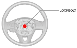
7.  Remove the lockbolt.

am2zzw00008145

8.  Remove the steering wheel using any commercially available puller.

Caution
•  Do not try to remove the steering wheel by hitting the shaft with a hammer. The steering column will be damaged.

9.  Remove the following parts:

(1)  Driver-side front scuff plate (See FRONT SCUFF PLATE REMOVAL/INSTALLATION.)
(2)  Driver-side front side trim (See FRONT SIDE TRIM REMOVAL/INSTALLATION.)
(3)  Bonnet release lever (See BONNET RELEASE LEVER AND RELEASE CABLE REMOVAL/INSTALLATION.)
(4)  Fuel-filler lid opener lever (See FUEL-FILLER LID OPENER AND LEVER REMOVAL/INSTALLATION.)

10.  Partially peel back the seaming welt.

11.  Remove the driver-side lower panel. (See DRIVER-SIDE LOWER PANEL REMOVAL/INSTALLATION.)

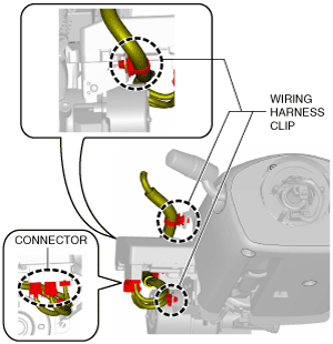
12.  Detach the wiring harness clips and connectors shown in the figure.

am2zzw00008146

13.  Remove the column cover. (See COLUMN COVER REMOVAL/INSTALLATION.)

14.  Remove the clock spring. (See CLOCK SPRING REMOVAL/INSTALLATION [STANDARD DEPLOYMENT CONTROL SYSTEM].) (See CLOCK SPRING REMOVAL/INSTALLATION [TWO-STEP DEPLOYMENT CONTROL SYSTEM].)

15.  Remove the light switch and the wiper and washer switch. (See LIGHT SWITCH REMOVAL/INSTALLATION.) (See WIPER AND WASHER SWITCH REMOVAL/INSTALLATION.)

16.  Remove the start stop unit. (See START STOP UNIT REMOVAL/INSTALLATION.)

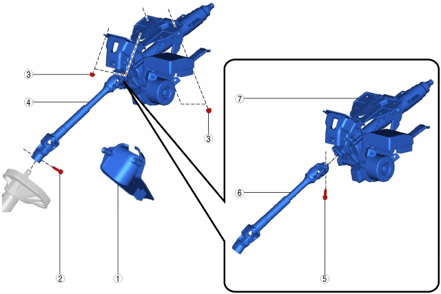
17.  Remove in the order indicated in the table.

am2zzw00008147

1
Joint cover
2
Joint bolt A
3
Nut
4
Steering column component
5
Joint bolt B
6
Intermediate shaft
7
Steering column


Steering Column Component Removal Note

Caution
•  Always lock the adjusting lever to prevent damage to the steering column. In addition, do not unlock the adjusting lever until the steering column installation is completed.
•  If the steering column is removed, remove it according to the procedure to prevent damage to intermediate shaft that could result if the steering column is removed in the incorrect order.

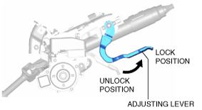
1.  Lock the adjusting lever.

am2zzw00008148

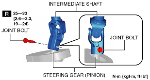
2.  Remove the joint bolt A, disconnect the intermediate shaft from the steering gear (pinion).

3.  Remove the nut, and then remove the steering column component from the dashboard member.


Installation

1.  Install the intermediate shaft to the steering column. (See INTERMEDIATE SHAFT REMOVAL/INSTALLATION.)

2.  Verify that the adjusting lever of the steering column component is locked.

am2zzw00008148

Caution
•  Do not unlock the adjusting lever until the steering column installation is completed to prevent damage to the steering column.

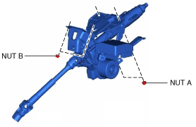
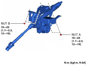
3.  Temporarily install the steering column component to the dashboard member using nuts A and B.

am2zzw00008149

4.  Tighten the nuts in the order of nut A and nut B.

Caution
•  If the steering column is installed, install it according to the procedure to prevent damage to intermediate shaft that could result if the steering column is installed in the incorrect order.
am2zzw00008150

5.  Insert the intermediate shaft into the steering gear (pinion) to the position shown in the figure and tighten it using a new joint bolt.

am2zzw00008151

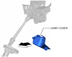
6.  Install the joint cover.

am2zzw00008152

7.  Install the start stop unit. (See START STOP UNIT REMOVAL/INSTALLATION.)

8.  Install the light switch and the wiper and washer switch. (See LIGHT SWITCH REMOVAL/INSTALLATION.) (See WIPER AND WASHER SWITCH REMOVAL/INSTALLATION.)

9.  Install the clock spring. (See CLOCK SPRING REMOVAL/INSTALLATION [STANDARD DEPLOYMENT CONTROL SYSTEM].) (See CLOCK SPRING REMOVAL/INSTALLATION [TWO-STEP DEPLOYMENT CONTROL SYSTEM].)

10.  Install the column cover. (See COLUMN COVER REMOVAL/INSTALLATION.)

11.  Assemble the wiring harness clips and connectors shown in the figure.

am2zzw00008146

12.  Install the driver-side lower panel. (See DRIVER-SIDE LOWER PANEL REMOVAL/INSTALLATION.)

13.  Assemble the seaming welt.

14.  Install the following part.

(1)  Fuel-filler lid opener lever (See FUEL-FILLER LID OPENER AND LEVER REMOVAL/INSTALLATION.)
(2)  Bonnet release lever (See BONNET RELEASE LEVER AND RELEASE CABLE REMOVAL/INSTALLATION.)
(3)  Driver-side front side trim (See FRONT SIDE TRIM REMOVAL/INSTALLATION.)
(4)  Driver-side front scuff plate (See FRONT SCUFF PLATE REMOVAL/INSTALLATION.)

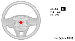
15.  With the steering wheel in the straight-ahead position, install the steering wheel using a new lockbolt.

am2zzw00008153

16.  Install the driver-side air bag module. (See DRIVER-SIDE AIR BAG MODULE INSTALLATION [STANDARD DEPLOYMENT CONTROL SYSTEM].) (See DRIVER-SIDE AIR BAG MODULE INSTALLATION [TWO-STEP DEPLOYMENT CONTROL SYSTEM].)

17.  Connect the negative battery cable. (See NEGATIVE BATTERY CABLE DISCONNECTION/CONNECTION.)

18.  If the steering column is replaced, perform the auto configuration using the following procedure.

(1)  Switch the ignition ON (engine off or on) and wait for 1 min or more.
(2)  Switch the ignition off and wait for 3 s or more.
(3)  Switch the ignition ON (engine off or on) and complete the EPS CM auto configuration.
(4)  Clear the DTC. (See CLEARING DTC [EPS CONTROL MODULE].)
(5)  Switch the ignition off and wait for 3 s or more.
(6)  Switch the ignition ON (engine off or on) and wait for 1 min or more.
(7)  Using the M-MDS, verify that DTCs U2300:54/U2300:55/U2300:56 are not displayed.
•  If DTCs U2300:54/U2300:55/U2300:56 are displayed, go to the DTC troubleshooting procedure. (See DTC U2300:54/U2300:55/U2300:56 [EPS CONTROL MODULE].)