 |
am6xuw00005574
POWER OUTER MIRROR INSPECTION
id091200002700
Mirror Glass Adjustment
1. Disconnect the negative battery cable. (See NEGATIVE BATTERY CABLE DISCONNECTION/CONNECTION.)
2. Remove the following parts:
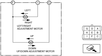
3. Apply battery positive voltage and connect the ground to the power outer mirror terminals and inspect the power outer mirror operation.
|
B+ terminal |
Ground terminal |
Operation |
|---|---|---|
|
C
|
F
|
Up
|
|
F
|
C
|
Down
|
|
I
|
F
|
Left
|
|
F
|
I
|
Right
|
am6xuw00005574
|
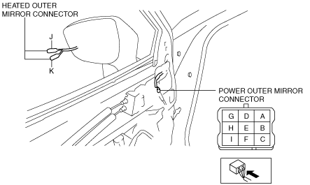
Heated Outer Mirror Inspection
1. Disconnect the negative battery cable. (See NEGATIVE BATTERY CABLE DISCONNECTION/CONNECTION.)
2. Remove the following parts:
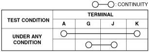
3. Verify that the continuity between heated outer mirror connector terminals is as indicated in the table.
am2zzw00007805
|
am2zzw00008558
|
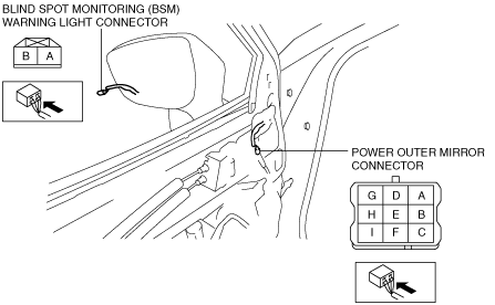
Blind Spot Monitoring (BSM) Warning Light Inspection
1. Disconnect the negative battery cable. (See NEGATIVE BATTERY CABLE DISCONNECTION/CONNECTION.)
2. Remove the following parts:
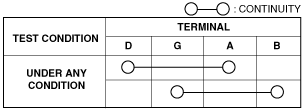
3. Verify that the continuity between blind spot monitoring (BSM) warning light connector terminals is as indicated in the table.
am2zzw00007806
|
am2zzw00008559
|