 |
am2zzw00007420
POWER BRAKE UNIT REMOVAL/INSTALLATION [R.H.D. (SKYACTIV-D 1.5)]
id0411008018u6
1. Remove the following parts:
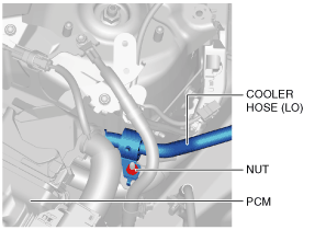
2. Remove the cooler hose (LO) installation nut. (See REFRIGERANT LINE REMOVAL/INSTALLATION [SKYACTIV-D 1.5].)
am2zzw00007420
|
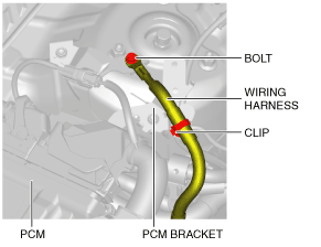
3. Remove the wiring harness from the PCM bracket. (See PCM REMOVAL/INSTALLATION [SKYACTIV-D 1.5].)
am2zzw00007421
|
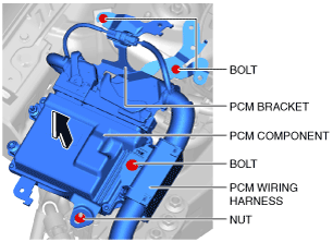
4. Remove the PCM bracket installation bolts and nut. (See PCM REMOVAL/INSTALLATION [SKYACTIV-D 1.5].)
am2zzw00007422
|
5. Remove the PCM wiring harness installation bolt.
6. Set the PCM component out of the way.
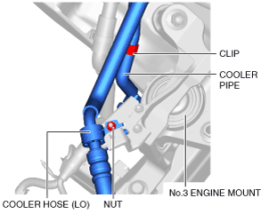
7. Remove the cooler hose (LO) installation nut. (See REFRIGERANT LINE REMOVAL/INSTALLATION [SKYACTIV-D 1.5].)
am2zzw00007423
|
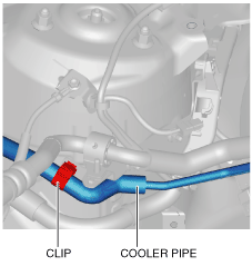
8. Detach the cooler pipe from the clip.
9. Detach the cooler pipe from the clip.
am2zzw00007424
|
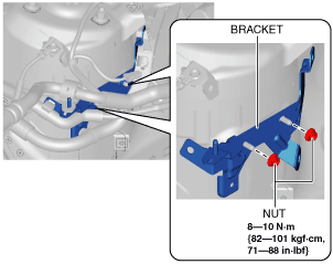
10. Remove the bracket installation nuts.
am2zzw00007425
|
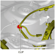
11. Remove the clip from the body.
am2zzw00007426
|
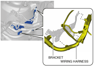
12. Remove the wiring harness from the bracket.
am2zzw00007427
|
13. Remove the bracket.
14. Remove the catalytic converter (DPF) insulator. (See EXHAUST SYSTEM REMOVAL/INSTALLATION [SKYACTIV-D 1.5].)
15. Disconnect the brake pipes from the DSC HU/CM. (See DSC HU/CM REMOVAL/INSTALLATION [R.H.D.].)
am2zzw00007428
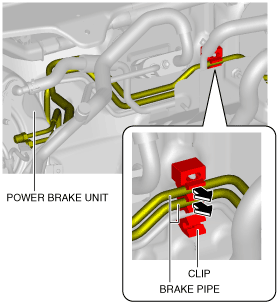
|
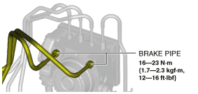
16. Detach the brake pipes from the clip.
am2zzw00007429
|
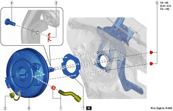
17. Remove in the order indicated in the table.
18. Install in the reverse order of removal.
19. After installation, add brake fluid, bleed the air, and inspect for fluid leakage. (See BRAKE FLUID AIR BLEEDING.)
20. Remove the brake switch. (See BRAKE PEDAL REMOVAL/INSTALLATION [R.H.D.].)
21. Inspect the brake pedal. (See BRAKE PEDAL INSPECTION.)
22. Install a new brake switch. (See BRAKE PEDAL REMOVAL/INSTALLATION [R.H.D.].)
am2zzw00007430
|
|
1
|
Vacuum hose, clamp
|
|
2
|
Power brake unit vacuum sensor connector
|
|
3
|
Snap pin
(See Snap Pin Installation Note.)
|
|
4
|
Clevis pin
|
|
5
|
Nut
|
|
6
|
Power brake unit
|
|
7
|
Gasket
|
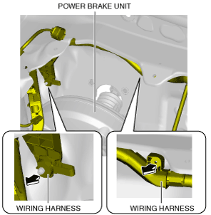
Power Brake Unit Removal Note
1. Move the power brake unit towards the front of the vehicle.
2. Remove the wiring harnesses shown in the figure from the body.
am2zzw00007431
|
3. Set the wiring harness out of the way.
4. Remove the power brake unit.
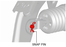
Snap Pin Installation Note
1. Install the snap pin as shown in the figure.
am2zzw00007433
|