|
1
|
INSPECT PAD SWITCH CONNECTOR
-
Warning
-
• Handling the component parts improperly can accidentally operate (deploy) the air bag modules and pre-tensioner seat belts, which may seriously injure you. Read the service warnings/cautions and the workshop manual before handling the air bag system components.
• Switch the ignition off.
• Disconnect the negative battery cable and wait for 1 min or more.
• Remove the glove compartment.
• Disconnect the PAD switch connector.
• Inspect the PAD switch connector. (Corrosion, damage, and disconnected pins)
• Is there any malfunction of the PAD switch connector?
|
Yes
|
Replace the malfunctioning part, then go to Step 6.
|
|
No
|
Go to the next step.
|
|
2
|
INSPECT PAD SWITCH CIRCUIT FOR SHORT TO GROUND
• Remove the column cover.
• Disconnect the clock spring connector.
• Remove the glove compartment.
• Disconnect the passenger-side air bag module connector.
• Disconnect the driver and passenger-side front seat connectors.
• Remove the B-pillar lower trim.
• Disconnect the driver and passenger-side pre-tensioner seat belt connectors.
• Disconnect the driver and passenger-side curtain air bag module connectors.
• Remove the rear package trim.
• Disconnect the rear pre-tensioner seat belt connectors.
• Disconnect the all SAS control module connectors.
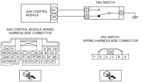
• Inspect for continuity between the following terminals (wiring harness-side) and body ground:
-
― SAS control module terminal 3P
― SAS control module terminal 3R
-
Note
-
• Inspect for continuity while shaking the wiring harness between the SAS control module and PAD switch.
• Is there continuity?
|
Yes
|
If there is a common connector:If there is no common connector:
Refer to the wiring diagram and verify whether or not there is a common connector between SAS control module terminal and PAD switch terminal.
• Determine the malfunctioning part by inspecting the common connector and the terminal for corrosion, damage, or pin disconnection, and the common wiring harness for a short to ground.
• Replace the malfunctioning part.
• Replace the wiring harness which has a short to ground.
Go to Step 6.
|
|
No
|
Go to the next step.
|
|
3
|
INSPECT PAD SWITCH CIRCUIT FOR OPEN CIRCUIT
• PAD switch and SAS control module connectors are disconnected.
• Inspect for continuity between the following terminals (wiring harness-side):
-
― PAD switch terminal C—SAS control module terminal 3P
― PAD switch terminal D—SAS control module terminal 3R
-
Note
-
• Inspect for continuity while shaking the wiring harness between the SAS control module and PAD switch.
• Is there continuity?
|
Yes
|
Go to the next step.
|
|
No
|
If there is a common connector:If there is no common connector:
Refer to the wiring diagram and verify whether or not there is a common connector between SAS control module terminal and PAD switch terminal.
• Determine the malfunctioning part by inspecting the common connector and the terminal for corrosion, damage, or pin disconnection, and the common wiring harness for an open circuit.
• Replace the malfunctioning part.
• Replace the wiring harness which has an open circuit.
Go to Step 6.
|
|
4
|
INSPECT PAD SWITCH CIRCUIT FOR SHORT TO POWER SUPPLY
• PAD switch and SAS control module connectors are disconnected.
• Connect the negative battery cable.
• Switch the ignition ON (engine off or on).
• Measure the voltage at the following terminals (wiring harness-side):
-
― SAS control module terminal 3P
― SAS control module terminal 3R
-
Note
-
• Measure the voltage while shaking the wiring harness between the SAS control module and PAD switch.
• Is the voltage 0 V?
|
Yes
|
Go to the next step.
|
|
No
|
If there is a common connector:If there is no common connector:
Refer to the wiring diagram and verify whether or not there is a common connector between SAS control module terminal and PAD switch terminal.
• Determine the malfunctioning part by inspecting the common connector and the terminal for corrosion, damage, or pin disconnection, and the common wiring harness for a short to power supply.
• Replace the malfunctioning part.
• Replace the wiring harness which has a short to power supply.
Go to Step 6.
|
|
5
|
INSPECT PAD SWITCH
• Inspect the PAD switch.
• Is it normal?
|
Yes
|
Go to the next step.
|
|
No
|
|
|
6
|
PERFORM SAS CONTROL MODULE DTC INSPECTION
• Switch the ignition off.
• Disconnect the negative battery cable and wait for 1min or more.
• Connect the SAS control module connectors.
• Reconnect all disconnected connectors.
• Connect the negative battery cable.
• Switch the ignition ON (engine off or on).
• Clear the DTC for the SAS control module using the M-MDS.
• Perform the DTC inspection for the SAS control module using the M-MDS.
• Are the same DTCs present?
|
Yes
|
Repeat the inspection from Step 1.
• If the malfunction recurs, replace the SAS control module.
|
|
No
|
DTC troubleshooting completed.
|