|
1
|
PERFORM INSTRUMENT CLUSTER DTC INSPECTION
• Are any DTCs present?
|
Yes
|
Perform the applicable DTC inspection. (See DTC TABLE [INSTRUMENT CLUSTER].) |
|
No
|
Go to the next step.
|
|
2
|
INSPECT SAS CONTROL MODULE CONNECTOR
-
Warning
-
• Handling the component parts improperly can accidentally operate (deploy) the air bag module, which may seriously injure you. Read the service warnings/cautions and the workshop manual before handling the air bag system components.
• Switch the ignition off.
• Disconnect the negative battery cable and wait for 1 min or more.
• Inspect the SAS control module connector terminal for poor connection (such as damaged/pulled-out pins, and corrosion).
• Is there any malfunction?
|
Yes
|
Replace the malfunctioning part, then go to the next step.
|
|
No
|
Go to the next step.
|
|
3
|
INSPECT INSTRUMENT CLUSTER CONNECTOR
• Inspect the instrument cluster terminal for poor connection (such as damaged/pulled-out pins, and corrosion).
• Is there any malfunction?
|
Yes
|
Replace the malfunctioning part, then go to Step 7.
|
|
No
|
Go to the next step.
|
|
4
|
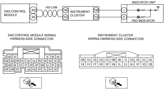
INSPECT SAS CONTROL MODULE CIRCUIT FOR SHORT TO GROUND
• Instrument cluster and SAS control module connectors are disconnected.
• Inspect for continuity between the following terminals (wiring harness-side) and body ground:
-
― SAS control module terminal 3Q
― SAS control module terminal 3S
-
Note
-
• Inspect for continuity while shaking the wiring harness between the SAS control module and instrument cluster.
• Is there continuity?
|
Yes
|
Replace the wiring harness for a possible short to ground, then go to Step 7.
|
|
No
|
Go to the next step.
|
|
5
|
INSPECT SAS CONTROL MODULE CIRCUIT FOR OPEN CIRCUIT
• Instrument cluster and SAS control module connectors are disconnected.
• Inspect for continuity between the following terminals (wiring harness-side):
-
― Instrument cluster terminal 1B—SAS control module terminal 3Q
― Instrument cluster terminal 1D—SAS control module terminal 3S
-
Note
-
• Inspect for continuity while shaking the wiring harness between the SAS control module and instrument cluster.
• Is there continuity?
|
Yes
|
Go to the next step.
|
|
No
|
Replace the wiring harness for a possible open circuit, then go to Step 7.
|
|
6
|
INSPECT SAS CONTROL MODULE CIRCUIT FOR SHORT TO POWER SUPPLY
• Instrument cluster and SAS control module connectors are disconnected.
• Switch the ignition ON (engine off or on).
• Measure the voltage at the following terminals (wiring harness-side):
-
― SAS control module terminal 3Q
― SAS control module terminal 3S
-
Note
-
• Measure the voltage while shaking the wiring harness between the SAS control module and instrument cluster.
• Is the voltage 0V?
|
Yes
|
Go to the next step.
|
|
No
|
Replace the wiring harness for a possible short to power supply, then go to the next step.
|
|
7
|
PERFORM SAS CONTROL MODULE DTC INSPECTION
• Switch the ignition to off.
• Disconnect the negative battery cable and wait for 1min or more.
• Connect the SAS control module connectors.
• Reconnect all disconnected connectors.
• Switch the ignition ON (engine off or on).
• Are the same DTCs present?
|
Yes
|
|
|
No
|
DTC troubleshooting completed.
|