 |
am2zzw00010493
DTC P0011:00, P0012:00 [SKYACTIV-G 1.3, SKYACTIV-G 1.5]
id0102q1710100
Details On DTCs (SKYACTIV-G 1.5 (with 4-2-1 exhaust system))
|
DESCRIPTION |
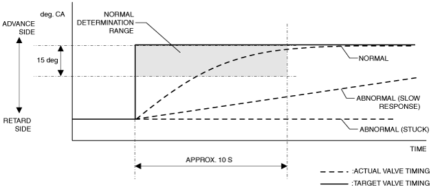
Electric variable valve timing control system: • P0011:00: Over-advanced
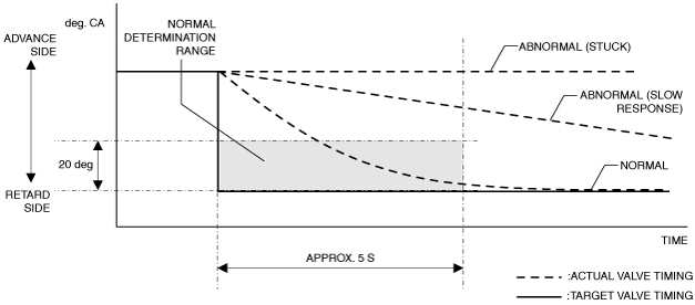
• P0012:00: Over-retarded
|
|
|---|---|---|
|
DETECTION CONDITION
|
Determination conditions
|
• P0011:00: For the advance amount from the maximum intake valve retard position, a condition in which the actual advance amount is larger than the target value continues for a specified period of time.
|
|
• P0012:00: For the advance amount from the maximum intake valve retard position, a condition in which the actual advance amount is smaller than the target value continues for a specified period of time.
|
||
|
Preconditions
|
• Battery voltage: above 11 V*1
• Engine speed: 5,000 rpm or less*1
• Engine coolant temperature: 20 °C {68 °F} or more*1
• The following DTCs are not detected:
*1: Value can be verified by displaying PIDs using M-MDS
|
|
|
Malfunction determination period
|
• 10 s period
|
|
|
Drive cycle
|
• 1
|
|
|
Self test type
|
• CMDTC self test
|
|
|
Sensor used
|
• CKP sensor
• Intake CMP sensor
|
|
|
FAIL-SAFE FUNCTION
|
• Not applicable
|
|
|
VEHICLE STATUS WHEN DTCs ARE OUTPUT
|
• Illuminates check engine light.
|
|
|
POSSIBLE CAUSE
|
• Electric variable valve timing motor/driver connectors or terminals malfunction
• Short to ground or open circuit in electric variable valve timing relay power supply circuit (without i-ELOOP)
• Short to ground or open circuit in electric variable valve timing relay power supply circuit (with i-ELOOP)
• Short to ground in wiring harness between the following terminals:
• Open circuit in wiring harness between the following terminals:
• PCM connector or terminals malfunction
• Electric variable valve timing relay malfunction
• Electric variable valve timing motor malfunction
• Electric variable valve timing actuator malfunction
• Timing chain malfunction
• Mis-detection of intake CMP sensor
• Mis-detection of CKP sensor
• PCM malfunction
|
|
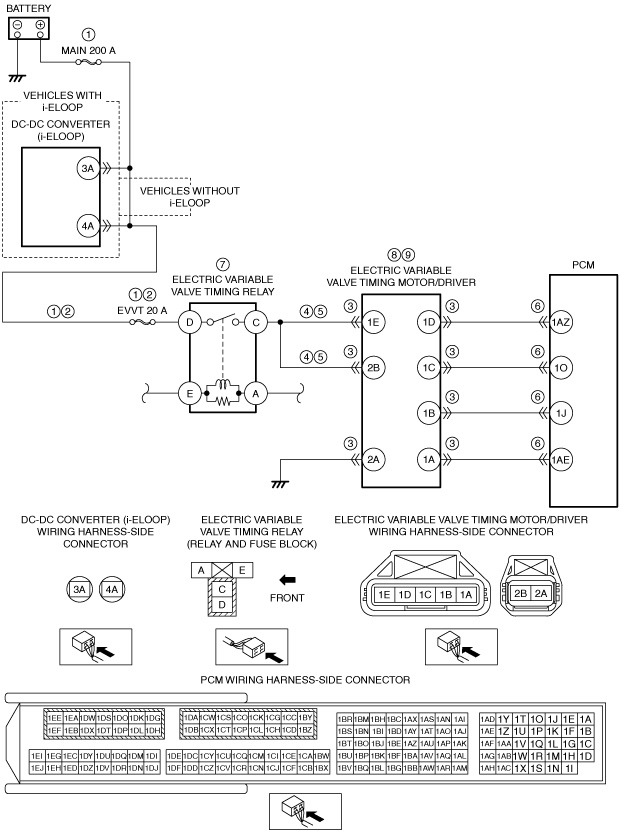
System Wiring Diagram (SKYACTIV-G 1.5 (with 4-2-1 exhaust system))
am2zzw00010493
|
Function Explanation (DTC Detection Outline) (SKYACTIV-G 1.5 (with 4-2-1 exhaust system))
am6zzw00011803
|
am3zzw00014488
|
Repeatability Verification Procedure (SKYACTIV-G 1.5 (with 4-2-1 exhaust system))
PID Item/Simulation Item Used In Diagnosis (SKYACTIV-G 1.5 (with 4-2-1 exhaust system))
PID/DATA monitor item table
|
Item |
Definition |
Unit |
Condition/Specification |
|---|---|---|---|
|
VT_IN_ACT
|
Actual exhaust variable valve timing control - Retard amount from max advance position
|
°
|
• Displays actual exhaust variable valve timing - Retard amount from max advance position
Idle (after warm up)
Racing (engine speed is 2,000 rpm)
|
|
VT_IN_DES
|
Target exhaust variable valve timing control - Retard amount from max advance position
|
°
|
• Displays target exhaust variable valve timing - Retard amount from max advance position
Idle (after warm up)
Racing (engine speed is 2,000 rpm)
|
Function Inspection Using M-MDS (SKYACTIV-G 1.5 (with 4-2-1 exhaust system))
|
STEP |
INSPECTION |
RESULTS |
ACTION |
|---|---|---|---|
|
1
|
PURPOSE: VERIFY RELATED SERVICE INFORMATION AVAILABILITY
• Verify related Service Information availability.
• Is any related Service Information available?
|
Yes
|
Perform repair or diagnosis according to the available Service Information.
• If the vehicle is not repaired, go to the next step.
|
|
No
|
Go to the next step.
|
||
|
2
|
PURPOSE: RECORD VEHICLE STATUS AT TIME OF DTC DETECTION TO UTILIZE WITH REPEATABILITY VERIFICATION
• Record the FREEZE FRAME DATA/snapshot data on the repair order.
|
—
|
Go to the next step.
|
|
3
|
PURPOSE: VERIFY IF DIAGNOSTIC RESULT IS AFFECTED BY OTHER RELATED DTCs OCCURRING
• Switch the ignition off, then ON (engine off).
• Perform the Pending Trouble Code Access Procedure and DTC Reading Procedure.
• Is the PENDING CODE/DTC P0010:00, P0335:00, P0340:00 or P1380:00 also present?
|
Yes
|
Go to the applicable DTC inspection.
Go to the next step.
|
|
No
|
Go to the next step.
|
||
|
4
|
PURPOSE: VERIFY CONFORMITY OF ACTUAL INTAKE VALVE TIMING
• Start the engine and idle it.
• Access the following PIDs using the M-MDS:
• Perform the following:
• Does the monitor value of the PID item VT_IN_ACT conform to the VT_IN_DES PID value?
|
Yes
|
Go to the next step.
|
|
No
|
Vehicles with i-ELOOP:
• Go to the troubleshooting procedure to perform the procedure from Step 2.
Vehicles without i-ELOOP:
• Go to the troubleshooting procedure to perform the procedure from Step 1.
|
||
|
5
|
PURPOSE: VERIFY CONNECTOR CONNECTIONS
• Start the engine.
• Access the VT_IN_ACT PID using the M-MDS.
• Does the PID value fluctuate when the following connectors are shaken?
|
Yes
|
Repair or replace the applicable wiring harness or connector parts.
Go to the troubleshooting procedure to perform the procedure from Step 13.
|
|
No
|
Vehicles with i-ELOOP:
• Go to the troubleshooting procedure to perform the procedure from Step 2.
Vehicles without i-ELOOP:
• Go to the troubleshooting procedure to perform the procedure from Step 1.
|
Troubleshooting Diagnostic Procedure (SKYACTIV-G 1.5 (with 4-2-1 exhaust system))
|
STEP |
INSPECTION |
RESULTS |
ACTION |
|---|---|---|---|
|
1
|
PURPOSE: INSPECT ELECTRIC VARIABLE VALVE TIMING RELAY POWER SUPPLY CIRCUIT FOR SHORT TO GROUND OR OPEN CIRCUIT
• Switch the ignition off.
• Remove the electric variable valve timing relay.
(See RELAY LOCATION.)
• Measure the voltage at the electric variable valve timing relay terminal D (wiring harness-side).
• Is the voltage B+?
|
Yes
|
Go to Step 3.
|
|
No
|
Inspect the MAIN 200 A fuse and EVVT 20 A fuse.
• If the fuse is blown:
• If the fuse is damaged:
• If all fuses are normal:
Go to Step 13.
|
||
|
2
|
PURPOSE: INSPECT ELECTRIC VARIABLE VALVE TIMING RELAY POWER SUPPLY CIRCUIT FOR SHORT TO GROUND OR OPEN CIRCUIT
• Switch the ignition off.
• Remove the electric variable valve timing relay.
(See RELAY LOCATION.)
• Measure the voltage at the electric variable valve timing relay terminal D (wiring harness-side).
• Is the voltage B+?
|
Yes
|
Go to the next step.
|
|
No
|
Remove the service plug.
Inspect the EVVT 20 A fuse.
• If the fuse is blown:
• If the fuse is damaged:
• If the fuse is normal:
Reinstall the service plug.
Go to Step 13.
|
||
|
3
|
PURPOSE: INSPECT ELECTRIC VARIABLE VALVE TIMING MOTOR/DRIVER CONNECTOR CONDITION
• Disconnect the electric variable valve timing motor/driver connector.
• Inspect for poor connection (such as damaged/pulled-out pins, corrosion).
• Is there any malfunction?
|
Yes
|
Repair or replace the connector and/or terminals, then go to Step 13.
|
|
No
|
Go to the next step.
|
||
|
4
|
PURPOSE: INSPECT ELECTRIC VARIABLE VALVE TIMING RELAY CONTROL CIRCUIT FOR SHORT TO GROUND
• Electric variable valve timing relay is removed.
• Verify that the electric variable valve timing motor/driver connector is disconnected.
• Inspect for continuity between electric variable valve timing relay terminal C (wiring harness-side) and body ground.
• Is there continuity?
|
Yes
|
Refer to the wiring diagram and verify whether or not there is a common connector between the following terminals:
• Electric variable valve timing relay terminal C—Electric variable valve timing motor/driver terminal 1E
• Electric variable valve timing relay terminal C—Electric variable valve timing motor/driver terminal 2B
If there is a common connector:
• Determine the malfunctioning part by inspecting the common connector and the terminal for corrosion, damage, or pin disconnection, and the common wiring harness for a short to ground.
• Repair or replace the malfunctioning part.
If there is no common connector:
• Repair or replace the wiring harness which has a short to ground.
Go to Step 13.
|
|
No
|
Go to the next step.
|
||
|
5
|
PURPOSE: INSPECT ELECTRIC VARIABLE VALVE TIMING RELAY CONTROL CIRCUIT FOR OPEN CIRCUIT
• Electric variable valve timing relay is removed.
• Verify that the electric variable valve timing motor/driver connector is disconnected.
• Inspect for continuity between the following terminals (wiring harness-side):
• Is there continuity?
|
Yes
|
Go to the next step.
|
|
No
|
Refer to the wiring diagram and verify whether or not there is a common connector between the following terminals:
• Electric variable valve timing relay terminal C—Electric variable valve timing motor/driver terminal 1E
• Electric variable valve timing relay terminal C—Electric variable valve timing motor/driver terminal 2B
If there is a common connector:
• Determine the malfunctioning part by inspecting the common connector and the terminal for corrosion, damage, or pin disconnection, and the common wiring harness for an open circuit.
• Repair or replace the malfunctioning part.
If there is no common connector:
• Repair or replace the wiring harness which has an open circuit.
Go to Step 13.
|
||
|
6
|
PURPOSE: INSPECT PCM CONNECTOR CONDITION
• Disconnect the PCM connector.
• Inspect for poor connection (such as damaged/pulled-out pins, corrosion).
• Is there any malfunction?
|
Yes
|
Repair or replace the connector and/or terminals, then go to Step 13.
|
|
No
|
Go to the next step.
|
||
|
7
|
PURPOSE: DETERMINE INTEGRITY OF ELECTRIC VARIABLE VALVE TIMING RELAY
• Inspect the electric variable valve timing relay.
(See RELAY INSPECTION.)
• Is there any malfunction?
|
Yes
|
Replace the electric variable valve timing relay, then go to Step 13.
|
|
No
|
Go to the next step.
|
||
|
8
|
PURPOSE: DETERMINE INTEGRITY OF ELECTRIC VARIABLE VALVE TIMING MOTOR
• Inspect the electric variable valve timing motor.
• Is there any malfunction?
|
Yes
|
Replace the electric variable valve timing motor/driver, then go to Step 13.
|
|
No
|
Go to the next step.
|
||
|
9
|
PURPOSE: DETERMINE INTEGRITY OF ELECTRIC VARIABLE VALVE TIMING ACTUATOR
• Inspect the electric variable valve timing actuator.
• Is there any malfunction?
|
Yes
|
Replace the electric variable valve timing actuator, then go to Step 13.
|
|
No
|
Go to the next step.
|
||
|
10
|
PURPOSE: VERIFY ASSEMBLY CONDITION OF TIMING CHAIN
• Verify the condition of the timing chain assembly (intake valve timing, looseness, jumping).
• Is there any malfunction?
|
Yes
|
Repair or replace the malfunctioning part.
Assemble the timing chain using the correct timing, then go to Step 13.
|
|
No
|
Go to the next step.
|
||
|
11
|
PURPOSE: VERIFY IF FOREIGN MATTER ON INTAKE CMP SENSOR DETECTION AREA AFFECTS DIAGNOSTIC RESULTS
• Visually inspect for intake CMP sensor.
• Is there foreign matter such as metallic dust on the intake CMP sensor detection area?
|
Yes
|
Remove the foreign matter, then go to Step 13.
|
|
No
|
Go to the next step.
|
||
|
12
|
PURPOSE: VERIFY IF FOREIGN MATTER ON CKP SENSOR DETECTION AREA AFFECTS DIAGNOSTIC RESULTS
• Visually inspect for CKP sensor.
• Is there foreign matter such as metallic dust on the CKP sensor detection area?
|
Yes
|
Remove the foreign matter, then go to the next step.
|
|
No
|
Go to the next step.
|
||
|
13
|
PURPOSE: VERIFICATION OF VEHICLE REPAIR COMPLETION
• Always reconnect all disconnected connectors.
• Clear the DTC from the PCM memory using the M-MDS.
• Implement the repeatability verification procedure.
• Perform the DTC Reading Procedure.
• Is the DTC P0011:00 or P0012:00 also present?
|
Yes
|
Repeat the inspection from Step 1.
• If the malfunction recurs, replace the PCM.
Go to the next step.
|
|
No
|
Go to the next step.
|
||
|
14
|
PURPOSE: VERIFY IF THERE IS ANY OTHER MALFUNCTION
• Is any other DTC or pending code stored?
|
Yes
|
Go to the applicable DTC inspection.
|
|
No
|
DTC troubleshooting completed.
|
Details On DTCs (SKYACTIV-G 1.3, SKYACTIV-G 1.5 (with 4-1 exhaust system))
|
DESCRIPTION |
Hydraulic variable valve timing control system: • P0011:00: Over-advanced
• P0012:00: Over-retarded
|
|
|---|---|---|
|
DETECTION CONDITION
|
Determination conditions
|
• P0011:00: A condition in which the actual intake valve timing advances (excess advance) compared to the target intake valve timing continues for the specified period.
|
|
• P0012:00: A condition in which the actual intake valve timing retards (excess retard) compared to the target intake valve timing continues for the specified period.
|
||
|
Preconditions
|
• Battery voltage: above 11 V*1
• Engine speed: 5,000 rpm or less*1
• Engine coolant temperature: 60 °C {140 °F} or more*1
• Hydraulic variable valve timing control: feedback mode
• The following DTCs are not detected:
*1: Value can be verified by displaying PIDs using M-MDS
|
|
|
Malfunction determination period
|
• 5 s period
|
|
|
Drive cycle
|
• 1
|
|
|
Self test type
|
• CMDTC self test
|
|
|
Sensor used
|
• CKP sensor
• Intake CMP sensor
|
|
|
FAIL-SAFE FUNCTION
|
• Not applicable
|
|
|
VEHICLE STATUS WHEN DTCs ARE OUTPUT
|
• Illuminates check engine light.
|
|
|
POSSIBLE CAUSE
|
• OCV malfunction
• Hydraulic variable valve timing actuator malfunction
• Timing chain malfunction
• Mis-detection of intake CMP sensor
• Mis-detection of CKP sensor
• Engine oil malfunction
• PCM malfunction
|
|
System Wiring Diagram (SKYACTIV-G 1.3, SKYACTIV-G 1.5 (with 4-1 exhaust system))
Function Explanation (DTC Detection Outline) (SKYACTIV-G 1.3, SKYACTIV-G 1.5 (with 4-1 exhaust system))
am2zzw00010494
|
am2zzw00010495
|
Repeatability Verification Procedure (SKYACTIV-G 1.3, SKYACTIV-G 1.5 (with 4-1 exhaust system))
PID Item Used In Diagnosis (SKYACTIV-G 1.3, SKYACTIV-G 1.5 (with 4-1 exhaust system))
PID/DATA monitor item table
|
Item |
Definition |
Unit |
Condition/Specification |
|---|---|---|---|
|
VT_EX_ACT
|
• Actual intake variable valve timing control - Advance amount from max retard position
|
°
|
• Displays actual intake variable valve timing - advance amount from max retard position
Idle (after warm up)
Racing (engine speed is 2,000 rpm)
|
|
VT_EX_DES
|
• Target intake variable valve timing control - Advance amount from max retard position
|
°
|
• Displays target intake variable valve timing - advance amount from max retard position
Idle (after warm up)
Racing (engine speed is 2,000 rpm)
|
Function Inspection Using M-MDS (SKYACTIV-G 1.3, SKYACTIV-G 1.5 (with 4-1 exhaust system))
|
STEP |
INSPECTION |
RESULTS |
ACTION |
|---|---|---|---|
|
1
|
PURPOSE: VERIFY RELATED SERVICE INFORMATION AVAILABILITY
• Verify related Service Information availability.
• Is any related Service Information available?
|
Yes
|
Perform repair or diagnosis according to the available Service Information.
• If the vehicle is not repaired, go to the next step.
|
|
No
|
Go to the next step.
|
||
|
2
|
PURPOSE: RECORD VEHICLE STATUS AT TIME OF DTC DETECTION TO UTILIZE WITH REPEATABILITY VERIFICATION
• Record the FREEZE FRAME DATA/snapshot data on the repair order.
|
—
|
Go to the next step.
|
|
3
|
PURPOSE: VERIFY IF DIAGNOSTIC RESULT IS AFFECTED BY OTHER RELATED DTCs OCCURRING
• Switch the ignition off, then ON (engine off).
• Perform the Pending Trouble Code Access Procedure and DTC Reading Procedure.
• Is the PENDING CODE/DTC P0335:00, P0340:00, P2088:00 or P2089:00 also present?
|
Yes
|
Go to the applicable PENDING CODE or DTC inspection.
Go to the next step.
|
|
No
|
Go to the next step.
|
||
|
4
|
PURPOSE: VERIFY CONFORMITY OF ACTUAL INTAKE VALVE TIMING AND DETERMINE IF MALFUNCTION IS CAUSED BY OCV OR CONNECTOR RELATED
• Start the engine and idle it.
• Access the following PIDs using the M-MDS:
• Perform the following:
• Does the monitor value of the PID item VT_EX_ACT conform to the VT_EX_DES PID value?
|
Yes
|
Go to the next step.
|
|
No
|
Go to the troubleshooting procedure to perform the procedure from Step 1.
|
||
|
5
|
PURPOSE: VERIFY CONNECTOR CONNECTIONS
• Start the engine.
• Access the VT_EX_ACT PID using the M-MDS.
• Does the PID value fluctuate when the following connectors are shaken?
|
Yes
|
Repair or replace the applicable wiring harness or connector parts.
Go to the troubleshooting procedure to perform the procedure from Step 8.
|
|
No
|
Go to the troubleshooting procedure to perform the procedure from Step 1.
|
Troubleshooting Diagnostic Procedure (SKYACTIV-G 1.3, SKYACTIV-G 1.5 (with 4-1 exhaust system))
|
STEP |
INSPECTION |
RESULTS |
ACTION |
|---|---|---|---|
|
1
|
PURPOSE: DETERMINE INTEGRITY OF HYDRAULIC VARIABLE VALVE TIMING ACTUATOR
• Inspect the hydraulic variable valve timing actuator.
• Is there any malfunction?
|
Yes
|
Replace the hydraulic variable valve timing actuator, then go to Step 8.
|
|
No
|
Go to the next step.
|
||
|
2
|
PURPOSE: VERIFY ASSEMBLY CONDITION OF TIMING CHAIN
• Verify the condition of the timing chain assembly (intake valve timing, looseness, jumping).
• Is there any malfunction?
|
Yes
|
Repair or replace the malfunctioning part.
Assemble the timing chain using the correct timing, then go to Step 8.
|
|
No
|
Go to the next step.
|
||
|
3
|
PURPOSE: VERIFY IF FOREIGN MATTER ON INTAKE CMP SENSOR DETECTION AREA AFFECTS DIAGNOSTIC RESULTS
• Visually inspect for intake CMP sensor.
• Is there foreign matter such as metallic dust on the intake CMP sensor detection area?
|
Yes
|
Remove the foreign matter, then go to Step 8.
|
|
No
|
Go to the next step.
|
||
|
4
|
PURPOSE: INSPECT IF INSUFFICIENT HYDRAULIC PRESSURE CAUSED BY USE OF UNSPECIFIED ENGINE OIL
• Is the specified engine oil being used?
|
Yes
|
Go to the next step.
|
|
No
|
Replace the engine oil with genuine motor oil, then go to Step 8.
|
||
|
5
|
PURPOSE: INSPECT ENGINE OIL LEVEL
• Inspect the engine oil level.
• Is the engine oil level sufficient?
|
Yes
|
Go to the next step.
|
|
No
|
Add genuine motor oil, then go to Step 8.
|
||
|
6
|
PURPOSE: INSPECT ENGINE OIL PRESSURE
• Inspect the engine oil pressure.
• Is there any malfunction?
|
Yes
|
Go to the next step.
|
|
No
|
Go to Step 8.
|
||
|
7
|
PURPOSE: VERIFY IF MALFUNCTION RELATED TO ENGINE OIL LEAK OR RESTRICTION AFFECTS DIAGNOSTIC RESULTS
• Start the engine.
• Verify if there is engine oil leakage in the oil passage or restriction.
• Is there engine oil leakage in the oil passage or restriction?
|
Yes
|
Repair or replace the malfunctioning part according to the inspection results.
Add genuine motor oil, then go to the next step.
|
|
No
|
Go to the next step.
|
||
|
8
|
PURPOSE: VERIFICATION OF VEHICLE REPAIR COMPLETION
• Always reconnect all disconnected connectors.
• Clear the DTC from the PCM memory using the M-MDS.
• Implement the repeatability verification procedure.
• Perform the Pending Trouble Code Access Procedure.
• Is the DTC P0011:00 or P0012:00 also present?
|
Yes
|
Repeat the inspection from Step 1.
• If the malfunction recurs, replace the PCM.
Go to the next step.
|
|
No
|
Go to the next step.
|
||
|
9
|
PURPOSE: VERIFY IF THERE IS ANY OTHER MALFUNCTION
• Is any other DTC or pending code stored?
|
Yes
|
Go to the applicable DTC inspection.
|
|
No
|
DTC troubleshooting completed.
|