 |
am2zzw00008260
FRONT CROSSMEMBER REMOVAL/INSTALLATION [SKYACTIV-G 1.3, SKYACTIV-G 1.5]
id0213008010f1
1. Remove the joint cover. (See STEERING WHEEL AND COLUMN REMOVAL/INSTALLATION.)
2. Disconnect the intermediate shaft from the steering gear and linkage. (See STEERING WHEEL AND COLUMN REMOVAL/INSTALLATION.)
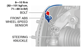
3. Remove the front ABS wheel-speed sensor from the steering knuckle.
am2zzw00008260
|
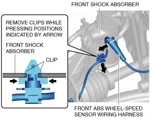
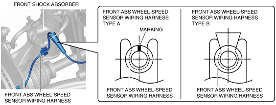
4. Remove the front ABS wheel-speed sensor wiring harness from the front shock absorber and set it aside so that it does not interfere with the servicing. (See Front ABS Wheel-Speed Sensor Wiring Harness Installation Note.)
am2zzw00008261
|
5. Remove the following parts:
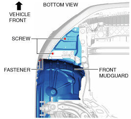
6. Remove the screws and the fasteners shown in the figure and set the front mudguard aside.
am2zzw00008262
|
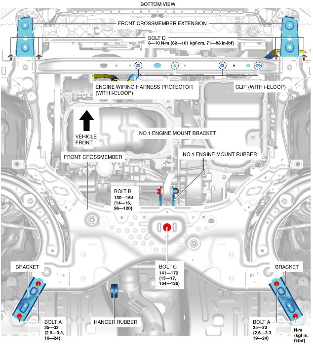
7. Remove engine wiring harness protector clips from the front crossmember. (With i-ELOOP)
am2zzw00008263
|
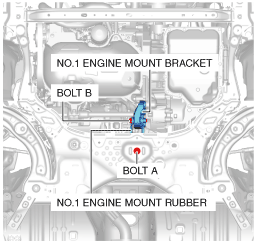
8. Remove bolts A.
9. Remove the brackets.
10. Disconnect the hanger rubber from the front crossmember and set it aside.
11. Remove bolt B.
12. Remove bolt C.
13. Disengage the No.1 engine mount rubber and the No.1 engine mount bracket. (See No.1 Engine Mount Rubber and No.1 Engine Mount Bracket Installation Note.)
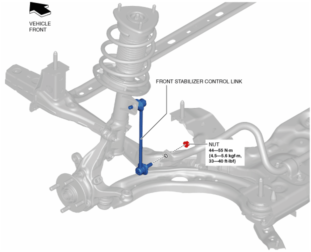
14. Disconnect the front stabilizer control link (front stabilizer side).
am2zzw00008264
|
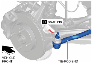
15. Remove the snap pin from the tie-rod end.
am2zzw00008265
|
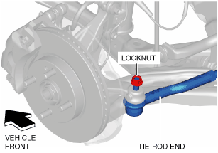
16. Loosen the locknut of the tie-rod end.
am2zzw00008266
|
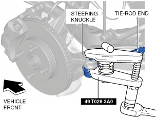
17. Using the SST, disengage the tie-rod end from the steering knuckle.
am2zzw00008267
|
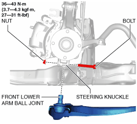
18. Remove the locknut from the tie-rod end.
19. Disconnect the tie-rod end from the steering knuckle.
20. Remove the bolt and nut from the front lower arm ball joint.
am2zzw00008268
|
21. Disconnect the front lower arm joint from the steering knuckle.
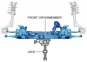
22. Support the front crossmember using a jack.
am2zzw00008269
|
23. Remove the bolts.
am2zzw00008270
|
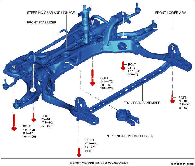
24. Lower the jack slowly and remove the front crossmember component. (See Front Crossmember Component Installation Note.)
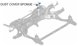
25. Remove the following parts:
26. Install in the reverse order of removal.
27. Inspect the wheel alignment and adjust it if necessary. (See FRONT WHEEL ALIGNMENT.)
Front Crossmember Component Installation Note
am2zzw00008295
|
Front Lower Arm Ball Joint Installation Note
1. Install the front lower arm ball joint to the steering knuckle, insert the bolts in the same direction for the right and left, then tighten them to the specified torque.
No.1 Engine Mount Rubber and No.1 Engine Mount Bracket Installation Note
1. Temporarily tighten bolt A shown in the figure.
am2zzw00012802
|
2. Temporarily tighten bolt B shown in the figure.
3. Tighten bolt A.
4. Tighten bolt B.
Front ABS Wheel-Speed Sensor Wiring Harness Installation Note
1. Install the front ABS wheel-speed sensor wiring harness as shown in the figure.
am2zzw00007231
|