 |
am2zzw00008255
STEERING GEAR AND LINKAGE REMOVAL/INSTALLATION
id061300801700
1. Remove the joint cover. (See STEERING WHEEL AND COLUMN REMOVAL/INSTALLATION.)
2. Disconnect the intermediate shaft from the steering gear and linkage. (See STEERING WHEEL AND COLUMN REMOVAL/INSTALLATION.)
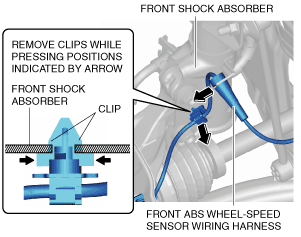
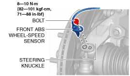
3. Remove the front ABS wheel-speed sensor from the steering knuckle.
am2zzw00008255
|
4. Remove the front ABS wheel-speed sensor wiring harness from the front shock absorber and set it aside so that it does not interfere with the servicing.
am2zzw00009087
|
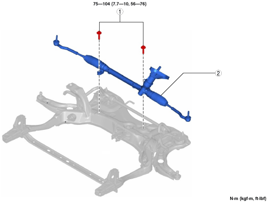
5. Remove the following parts:
6. Remove in the order indicated in the table.
7. Install in the reverse order of removal.
8. After installation, inspect the front wheel alignment. (See FRONT WHEEL ALIGNMENT.)
L.H.D.
am2zzw00008158
|
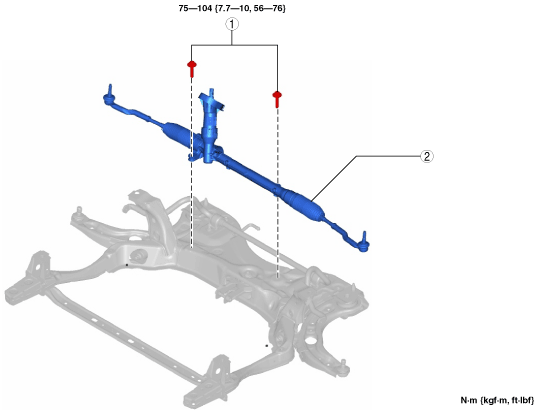
R.H.D.
am2zzw00008159
|
|
1
|
Steering gear and linkage installation bolt
|
|
2
|
Steering gear and linkage
|
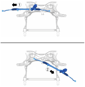
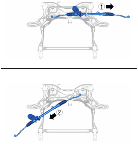
Steering Gear and Linkage Removal Note
1. Remove the steering gear and linkage installation bolts, move the steering gear and linkage in the direction and order of the arrows shown in the figure, and then remove it.
L.H.D.
am2zzw00008160
|
R.H.D.
adejjw00010124
|