 |
am2zzw00009432
AUTOMATIC TRANSAXLE REMOVAL/INSTALLATION [EW6A-EL]
id0517l2117200
Procedure Before i-ELOOP-Related Part Servicing
Removal
1. Disconnect the negative battery cable. (See NEGATIVE BATTERY CABLE DISCONNECTION/CONNECTION.)
2. Remove the splash shield (LH). (See SPLASH SHIELD REMOVAL/INSTALLATION.)
3. Disconnect the service plug. (With i-ELOOP) (See SERVICE PLUG DISCONNECTION/CONNECTION [i-ELOOP].)
4. Remove the air cleaner, air hose and fresh air duct as a single unit. (See INTAKE-AIR SYSTEM REMOVAL/INSTALLATION [SKYACTIV-D 1.5].)
5. Remove the battery and battery tray. (See BATTERY REMOVAL/INSTALLATION [SKYACTIV-D 1.5].)
6. Remove the DC-DC converter (i-ELOOP). (With i-ELOOP) (See DC-DC CONVERTER (i-ELOOP) REMOVAL/INSTALLATION [WITH i-ELOOP (SKYACTIV-D 1.5)].)
7. Remove the turbocharger air outlet pipe. (See INTAKE-AIR SYSTEM REMOVAL/INSTALLATION [SKYACTIV-D 1.5].)
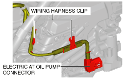
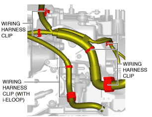
8. Disconnect the wiring harness clip from the transaxle.
am2zzw00009432
|
9. Disconnect the electric AT oil pump connector and wiring harness clip from the transaxle.
am2zzw00009433
|
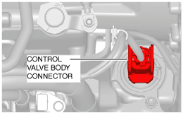
10. Disconnect the control valve body connector.
am2zzw00009434
|
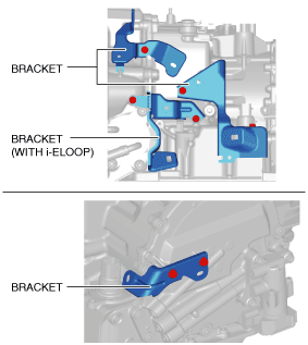
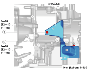
11. Remove the bracket from the transaxle.
am2zzw00009435
|
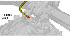
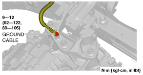
12. Disconnect the ground cable.
am2zzw00009436
|
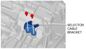
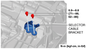
13. Disconnect the clip and selector cable from the transaxle. (See AUTOMATIC TRANSAXLE SHIFT MECHANISM REMOVAL/INSTALLATION.)
14. Remove the selector cable bracket.
am2zzw00009438
|
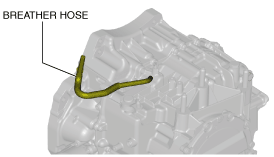
15. Disconnect the breather hose from the transaxle.
am2zzw00009439
|
16. Remove the joint cover. (See STEERING WHEEL AND COLUMN REMOVAL/INSTALLATION.)
17. Disconnect the intermediate shaft from the steering gear and linkage. (See STEERING WHEEL AND COLUMN REMOVAL/INSTALLATION.)
18. Remove the front tires. (See GENERAL PROCEDURES (SUSPENSION).)
19. Remove the front under cover No.2. (See FRONT UNDER COVER No.2 REMOVAL/INSTALLATION.)
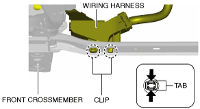
20. Disconnect the wiring harness from the front crossmember. (With i-ELOOP)
am2zzw00009440
|
21. Remove the front under cover No.1. (See FRONT UNDER COVER No.1 REMOVAL/INSTALLATION.)
22. Drain the engine coolant and water-cooled charge air cooler coolant. (See ENGINE COOLANT REPLACEMENT [SKYACTIV-D 1.5].) (See WATER-COOLED CHARGE AIR COOLER COOLANT REPLACEMENT [SKYACTIV-D 1.5].)
23. Drain the ATF. (See AUTOMATIC TRANSAXLE FLUID (ATF) REPLACEMENT [EW6A-EL].)
24. Remove the electric water pump. (See ELECTRIC WATER PUMP REMOVAL/INSTALLATION [SKYACTIV-D 1.5].)
25. Remove the starter. (See STARTER REMOVAL/INSTALLATION [SKYACTIV-D 1.5].)
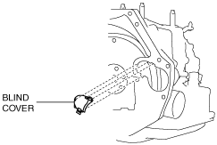
26. Remove the blind cover.
am2zzw00009441
|
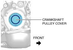
27. Remove the crankshaft pulley cover.
am2zzw00009442
|
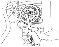
28. Hold the crankshaft pulley to prevent torque converter from rotating.
am3uuw00002582
|
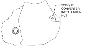
29. Remove the torque converter installation nuts from the starter installation hole.
am2zzw00009443
|
30. Disconnect the front ABS wheel-speed sensors from the steering knuckles. (See FRONT ABS WHEEL-SPEED SENSOR REMOVAL/INSTALLATION.)
31. Disconnect the clips securing the brake hose from the front shock absorbers. (See BRAKE HOSE (FRONT) REMOVAL/INSTALLATION.)
32. Disconnect the tie-rod end ball joints from the steering knuckles. (See FRONT CROSSMEMBER REMOVAL/INSTALLATION [SKYACTIV-D 1.5].)
33. Disconnect the front lower arms from the steering knuckles. (See FRONT LOWER ARM REMOVAL/INSTALLATION.)
34. Disconnect the front stabilizer control links from the front stabilizer. (See FRONT STABILIZER REMOVAL.)
35. Disconnect the front drive shaft (LH) from the transaxle. (See FRONT DRIVE SHAFT REMOVAL/INSTALLATION.)
36. Disconnect the front drive shaft (RH) from the transaxle. (See FRONT DRIVE SHAFT REMOVAL/INSTALLATION.)
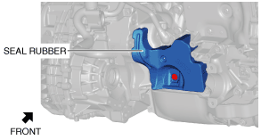
37. Remove the seal rubber.
am2zzw00009444
|
38. Remove the insulator. (See EXHAUST SYSTEM REMOVAL/INSTALLATION [SKYACTIV-D 1.5].)
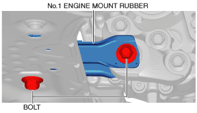
39. Remove the front crossmember component and No.1 engine mount rubber as a single unit. (See FRONT CROSSMEMBER REMOVAL/INSTALLATION [SKYACTIV-D 1.5].)
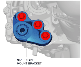
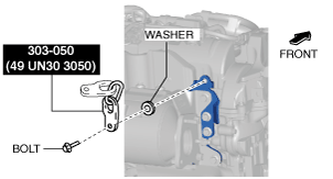
40. Remove the No.1 engine mount bracket from the transaxle.
am2zzw00009445
|
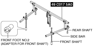
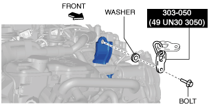
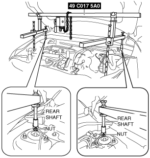
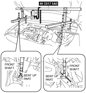
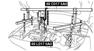
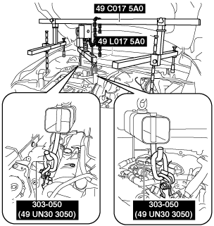
41. Install the SST (49 C017 5A0, 49 UN30 3050, 49 L017 5A0) using the following procedures.
am6zzw00010924
|
am2zzw00009446
|
am2zzw00009447
|
am2zzw00009448
|
am2zzw00009449
|
am2zzw00009450
|
am2zzw00009451
|
am2zzw00009452
|
am2zzw00009453
|
am2zzw00009454
|
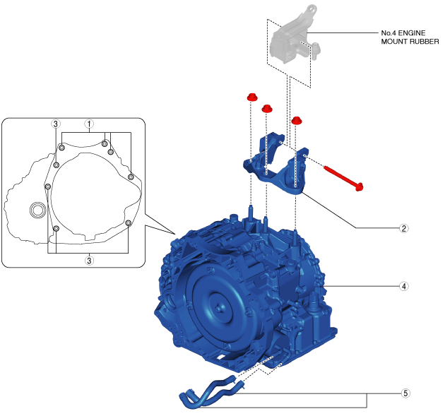
42. Remove in the order shown in the table.
am2zzw00009455
|
|
1
|
Transaxle mounting bolts (upper side)
|
|
2
|
No.4 engine mount bracket
|
|
3
|
Transaxle mounting bolts (lower side)
|
|
4
|
Transaxle
|
|
5
|
Water hose (Automatic transaxle replacement)
|
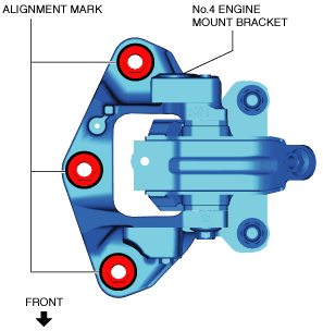
No.4 engine mount bracket removal note
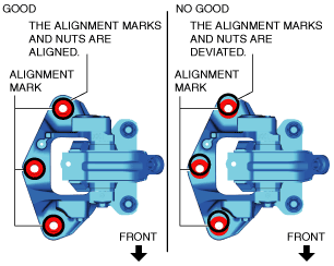
1. Place alignment marks on the locations shown in the figure so that they can be assembled to the same positions as before removal.
am2zzw00009456
|
2. Remove the No.4 engine mount bracket.
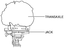
Transaxle mounting bolt (lower side) removal note
1. Adjust the SST (49 C017 5A0) and lean the engine toward the transaxle.
am2zzw00009453
|
2. Support the transaxle on a jack.
am2zzw00009457
|
3. Remove the transaxle mounting bolts (lower side).
4. Remove the transaxle.
Installation
1. Install the water hose. (Automatic Transaxle Replacement) (See OIL COOLER REMOVAL/INSTALLATION [EW6A-EL].)
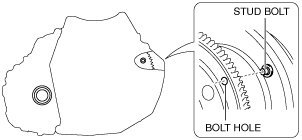
2. Verify that the torque converter stud bolts are inserted into the drive plate bolt holes from the starter installation hole.
am2zzw00009458
|
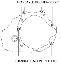
3. Install the transaxle mounting bolts.
am2zzw00009459
|
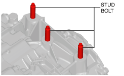
4. Tighten the stud bolts for the transaxle.
am2zzw00009460
|
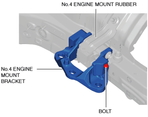
5. Install the No.4 engine mount bracket to No.4 engine mount rubber, and temporarily tighten the installation bolt.
am2zzw00009461
|
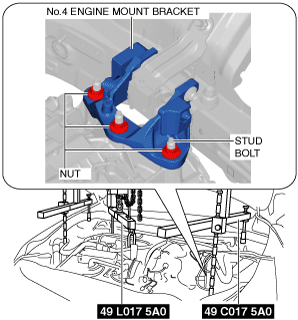
6. Lift up the manual transaxle using the SST (49 C017 5A0), pass the stud bolt through the No.4 engine mount bracket, and temporarily tighten the No.4 engine mount bracket installation nuts.
am2zzw00009462
|
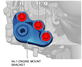
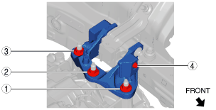
7. Install the No.1 engine mount bracket, and tighten the installation bolts in the order shown in the figure.
am2zzw00009463
|
8. Install the front crossmember component and No.1 engine mount rubber as a single unit. (See FRONT CROSSMEMBER REMOVAL/INSTALLATION [SKYACTIV-D 1.5].)
9. Temporarily tighten the No.1 engine mount rubber installation bolts.
am2zzw00009464
|
10. Align the alignment marks on the No.4 engine mount bracket and nuts, and temporarily tighten the nuts shown in the figure.
am2zzw00009465
|
11. Tighten the No.4 engine mount bracket installation nuts and bolt in the order shown in the figure.
am2zzw00009466
|
|
No. |
Tightening torque |
|---|---|
|
1, 2, 3
|
92—116 N·m {9.4—11 kgf·m, 69—85 ft·lbf}
|
|
4
|
81—99 N·m {8.3—10 kgf·m, 60—73 ft·lbf}
|
12. Remove the SST (49 C017 5A0, 49 L017 5A0).
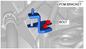
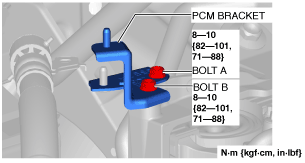
13. Install the PCM bracket in the following order.
am2zzw00009467
|
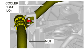
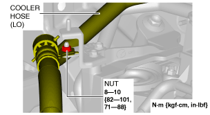
14. Install the cooler hose (LO).
am2zzw00009468
|
15. Install the PCM component. (See PCM REMOVAL/INSTALLATION [SKYACTIV-D 1.5].)
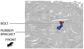
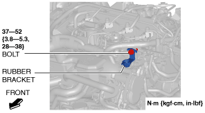
16. Install the rubber bracket.
am2zzw00009469
|
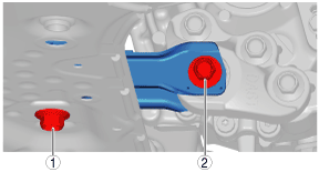
17. Tighten the No.1 engine mount rubber installation bolts in the order shown in the figure.
adejjw00012406
|
|
No. |
Tightening torque |
|---|---|
|
1
|
141—172 N·m {15—17 kgf·m, 104—126 ft·lbf}
|
|
2
|
130—164 N·m {14—16 kgf·m, 96—120 ft·lbf}
|
18. Fix the crankshaft pulley to lock the torque converter against rotation.
am3uuw00002582
|
19. Tighten the torque converter installation nuts.
am2zzw00009443
|
20. Install the blind cover.
am2zzw00009441
|
21. Install the starter. (See STARTER REMOVAL/INSTALLATION [SKYACTIV-D 1.5].)
22. Install the crankshaft pulley cover.
am2zzw00009442
|
23. Install the electric water pump. (See ELECTRIC WATER PUMP REMOVAL/INSTALLATION [SKYACTIV-D 1.5].)
24. Install the insulator. (See EXHAUST SYSTEM REMOVAL/INSTALLATION [SKYACTIV-D 1.5].)
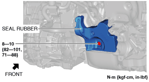
25. Install the seal rubber.
am2zzw00009470
|
26. Install the front drive shaft (RH) to the transaxle. (See FRONT DRIVE SHAFT REMOVAL/INSTALLATION.)
27. Install the front drive shaft (LH) to the transaxle. (See FRONT DRIVE SHAFT REMOVAL/INSTALLATION.)
28. Install the front stabilizer control links to the front stabilizer. (See FRONT STABILIZER INSTALLATION.)
29. Install the front lower arms to the steering knuckles. (See FRONT LOWER ARM REMOVAL/INSTALLATION.)
30. Install the tie-rod ends to the steering knuckles. (See FRONT CROSSMEMBER REMOVAL/INSTALLATION [SKYACTIV-D 1.5].)
31. Install the clips securing the brake hose to the front shock absorbers. (See BRAKE HOSE (FRONT) REMOVAL/INSTALLATION.)
32. Install the front ABS wheel-speed sensors to the steering knuckles. (See FRONT ABS WHEEL-SPEED SENSOR REMOVAL/INSTALLATION.)
33. Install the front under cover No.1. (See FRONT UNDER COVER No.1 REMOVAL/INSTALLATION.)
34. Connect the wiring harness from the front crossmember. (With i-ELOOP)
am2zzw00009440
|
35. Install the front tires. (See GENERAL PROCEDURES (SUSPENSION).)
36. Install the intermediate shaft to the steering gear and linkage. (See STEERING WHEEL AND COLUMN REMOVAL/INSTALLATION.)
37. Install the joint cover. (See STEERING WHEEL AND COLUMN REMOVAL/INSTALLATION.)
38. Connect the breather hose to the transaxle.
am2zzw00009439
|
39. Install the selector cable bracket.
am2zzw00009471
|
40. Connect the selector cable and clip to the transaxle. (See AUTOMATIC TRANSAXLE SHIFT MECHANISM REMOVAL/INSTALLATION.)
41. Install the ground cable to the No.4 engine mount bracket.
am2zzw00009472
|
42. Install the bracket installation bolts in the order shown in the figure.
am2zzw00009473
|
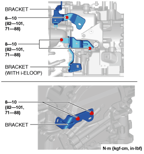
43. Install the brackets to the transaxle.
am2zzw00009474
|
44. Connect the control valve body connector.
am2zzw00009434
|
45. Connect the electric AT oil pump connector and wiring harness clip from the transaxle.
am2zzw00009433
|
46. Connect the wiring harness clip to the transaxle.
am2zzw00009432
|
47. Install the DC-DC converter (i-ELOOP). (With i-ELOOP) (See DC-DC CONVERTER (i-ELOOP) REMOVAL/INSTALLATION [WITH i-ELOOP (SKYACTIV-D 1.5)].)
48. Connect the service plug. (With i-ELOOP) (See SERVICE PLUG DISCONNECTION/CONNECTION [i-ELOOP].)
49. Install the splash shield (LH). (See SPLASH SHIELD REMOVAL/INSTALLATION.)
50. Install the battery and battery tray. (See BATTERY REMOVAL/INSTALLATION [SKYACTIV-D 1.5].)
51. Install the air cleaner, air hose and fresh air duct as a single unit. (See INTAKE-AIR SYSTEM REMOVAL/INSTALLATION [SKYACTIV-D 1.5].)
52. Connect the negative battery cable. (See NEGATIVE BATTERY CABLE DISCONNECTION/CONNECTION.)
53. Add the engine coolant and water-cooled charge air cooler coolant. (See ENGINE COOLANT REPLACEMENT [SKYACTIV-D 1.5].) (See WATER-COOLED CHARGE AIR COOLER COOLANT REPLACEMENT [SKYACTIV-D 1.5].)
54. Add the ATF. (See AUTOMATIC TRANSAXLE FLUID (ATF) REPLACEMENT [EW6A-EL].)
55. Perform the “TCM configuration” (Automatic Transaxle Replacement). (See TCM CONFIGURATION [EW6A-EL].)
56. Perform the “Initial Learning” (automatic transaxle Replacement). (See INITIAL LEARNING [EW6A-EL].)
57. Perform the “Mechanical System Test”. (See MECHANICAL SYSTEM TEST [EW6A-EL].)
58. Install the front under cover No.2. (See FRONT UNDER COVER No.2 REMOVAL/INSTALLATION.)