AUTOMATIC TRANSAXLE SHIFT MECHANISM REMOVAL/INSTALLATION
id051800296900
Selector Lever Removal/Installation
1. Disconnect the negative battery cable. (See NEGATIVE BATTERY CABLE DISCONNECTION/CONNECTION.)
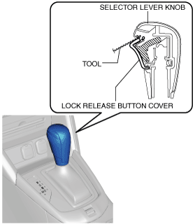
2. Perform the following procedure to remove the selector lever knob.
-
Note
-
• If the servicing is difficult, release the shift lock manually and shift the selector lever to the N position.
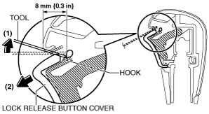
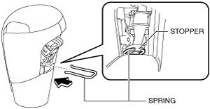
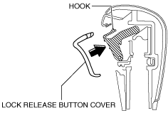
- (1) Insert the tool (width: 4 mm {0.2 in} or less, thickness: 1 mm {0.04 in} or less) as shown in the figure.
-
- (2) Move the tool in the direction of arrow (1) in the figure and detach the hook. Move the lock release button cover in the direction of arrow (2) in the figure and remove it.
-
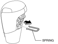
- (3) Remove the spring.
-
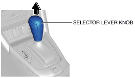
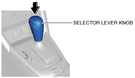
- (4) Remove the selector lever knob.
-
3. Remove the following parts:
- (1) Center console tray (See CENTER CONSOLE TRAY REMOVAL/INSTALLATION.)
-
- (2) Shift bezel (See SHIFT BEZEL REMOVAL/INSTALLATION.)
-
- (3) Upper panel (See UPPER PANEL REMOVAL/INSTALLATION.)
-
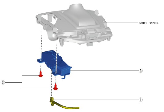
- (4) Shift panel (See SHIFT PANEL REMOVAL/INSTALLATION.)
-
- (5) Console side panel (See CONSOLE SIDE PANEL REMOVAL/INSTALLATION.)
-
- (6) Front console box (See FRONT CONSOLE BOX REMOVAL/INSTALLATION.)
-
- (7) CD player (with CD player) (See CD PLAYER REMOVAL.)
-
- (8) DVD/CD player (with DVD/CD player) (See DVD/CD PLAYER REMOVAL.)
-
- (9) Front console (See FRONT CONSOLE REMOVAL/INSTALLATION.)
-
- (10) Side wall (See SIDE WALL REMOVAL/INSTALLATION.)
-
- (11) Rear console (See REAR CONSOLE REMOVAL/INSTALLATION.)
-
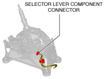
4. Disconnect the selector lever component connector.
5. Remove the selector cable (selector lever side). (See Selector Cable Removal/Installation [CW6A-EL].) (See Selector Cable Removal/Installation [EW6A-EL].)
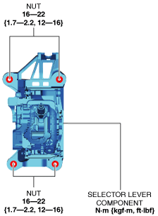
6. Remove the nuts from the selector lever component.
7. Remove the selector lever component.
8. Install the selector lever component.
9. Install the nuts from the selector lever component.
10. Install the selector cable (selector lever side). (See Selector Cable Removal/Installation [CW6A-EL].) (See Selector Cable Removal/Installation [EW6A-EL].)
11. Connect the selector lever component connector.
12. Install the following parts:
- (1) Rear console (See REAR CONSOLE REMOVAL/INSTALLATION.)
-
- (2) Side wall (See SIDE WALL REMOVAL/INSTALLATION.)
-
- (3) Front console (See FRONT CONSOLE REMOVAL/INSTALLATION.)
-
- (4) DVD/CD player (with DVD/CD player) (See DVD/CD PLAYER INSTALLATION.)
-
- (5) CD player (with CD player) (See CD PLAYER INSTALLATION.)
-
- (6) Front console box (See FRONT CONSOLE BOX REMOVAL/INSTALLATION.)
-
- (7) Console side panel (See CONSOLE SIDE PANEL REMOVAL/INSTALLATION.)
-
- (8) Shift panel (See SHIFT PANEL REMOVAL/INSTALLATION.)
-
- (9) Upper panel (See UPPER PANEL REMOVAL/INSTALLATION.)
-
- (10) Shift bezel (See SHIFT BEZEL REMOVAL/INSTALLATION.)
-
- (11) Center console tray (See CENTER CONSOLE TRAY REMOVAL/INSTALLATION.)
-
13. Perform the following procedure to install the selector lever knob.
- (1) Install the spring to the selector lever knob.
-
-
Caution
-
• Install the spring so that it is stopped by the stopper.
- (2) Install the selector lever knob to the selector lever component.
-
- (3) Install the lock release button cover so that it engages with the hook of the selector lever knob.
-
- (4) Pull the select lever knob upward and verify that it is securely installed.
-
14. Connect the negative battery cable. (See NEGATIVE BATTERY CABLE DISCONNECTION/CONNECTION.)
Indicator Removal/Installation
1. Disconnect the negative battery cable. (See NEGATIVE BATTERY CABLE DISCONNECTION/CONNECTION.)
2. Remove the center console tray. (See CENTER CONSOLE TRAY REMOVAL/INSTALLATION.)
3. Remove the shift bezel. (See SHIFT BEZEL REMOVAL/INSTALLATION.)
4. Remove the upper panel. (See UPPER PANEL REMOVAL/INSTALLATION.)
5. Remove the selector lever knob. (See Selector Lever Removal/Installation.)
6. Remove the shift panel. (See SHIFT PANEL REMOVAL/INSTALLATION.)
7. Remove in the order indicated in the table.
8. Install in the reverse order of removal.
|
1
|
Connector
|
|
2
|
Screw
|
|
3
|
Indicator
|
Selector Cable Removal/Installation [CW6A-EL]
1. Disconnect the negative battery cable. (See NEGATIVE BATTERY CABLE DISCONNECTION/CONNECTION.)
2. Remove the selector lever knob. (See Selector Lever Removal/Installation.)
3. Perform the following procedure to remove the selector cable (selector lever side).
- (1) Remove the center console tray. (See CENTER CONSOLE TRAY REMOVAL/INSTALLATION.)
-
- (2) Remove the shift bezel. (See SHIFT BEZEL REMOVAL/INSTALLATION.)
-
- (3) Remove the upper panel. (See UPPER PANEL REMOVAL/INSTALLATION.)
-
- (4) Remove the shift panel. (See SHIFT PANEL REMOVAL/INSTALLATION.)
-
- (5) Remove the console side panel. (See CONSOLE SIDE PANEL REMOVAL/INSTALLATION.)
-
- (6) Remove the front console box. (See FRONT CONSOLE BOX REMOVAL/INSTALLATION.)
-
- (7) Remove the CD player. (with CD player) (See CD PLAYER REMOVAL.) (See CD PLAYER INSTALLATION.)
-
- (8) Remove the DVD/CD player. (with DVD/CD player) (See DVD/CD PLAYER REMOVAL.) (See DVD/CD PLAYER INSTALLATION.)
-
- (9) Remove the front console. (See FRONT CONSOLE REMOVAL/INSTALLATION.)
-
- (10) Remove the side wall. (See SIDE WALL REMOVAL/INSTALLATION.)
-
- (11) Remove the rear console. (See REAR CONSOLE REMOVAL/INSTALLATION.)
-
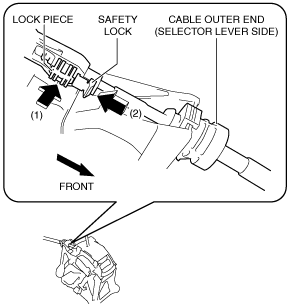
- (12) Pull out the safety lock in the direction of the arrow (1) shown in the figure, pull out the lock piece in the direction of the arrow (2) shown in the figure, and release the lock. (See Selector Cable (Selector Lever Side) Installation Note.)
-
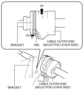
- (13) While pressing the cable outer end tab (selector lever side) in the direction of the arrow (3) shown in the figure, lift up cable outer end (selector lever side) in the direction of the arrow (4) shown in the figure to detach the cable outer end tab (selector lever side) from the bracket.
-
- (14) Remove the cable outer end (selector lever side) from the bracket.
-
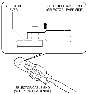
- (15) Remove the selector cable end (selector lever side) from the selector lever.
-
4. Perform the following procedure to remove the selector cable (transaxle side).
- (1) Remove the air cleaner case. (See INTAKE-AIR SYSTEM REMOVAL/INSTALLATION [SKYACTIV-G 1.3, SKYACTIV-G 1.5].)
-
- (2) Remove the battery tray. (See BATTERY REMOVAL/INSTALLATION [SKYACTIV-G 1.3, SKYACTIV-G 1.5].)
-
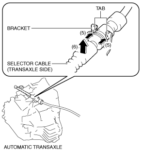
- (3) While pressing the bracket tab in the direction of the arrow (5) shown in the figure, lift up the cable outer end (transaxle side) in the direction of the arrow (6) shown in the figure to detach the bracket tab from the cable outer end (transaxle side).
-
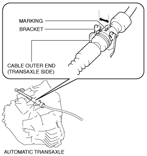
- (4) Remove the cable outer end (transaxle side) from the bracket. (See Cable Outer End (Transaxle Side) Installation Note.)
-
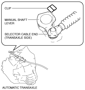
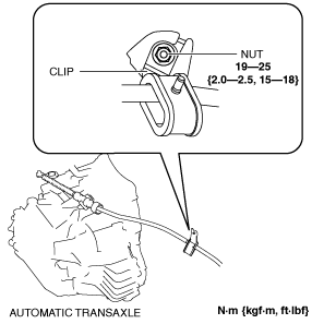
- (5) Remove the clip from the selector cable end (transaxle side). (See Selector Cable End (Transaxle Side) Installation Note.)
-
-
Caution
-
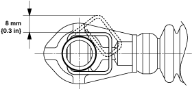
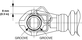
• Pull the clip within the range shown in the figure. If the clip is pulled excessively, it could deform and no longer function.
- (6) Remove the selector cable end (transaxle side) from the manual shaft lever.
-
5. Remove the clip as shown in the figure and remove the nut.
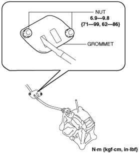
6. Remove the grommet as shown in the figure and remove the nuts.
7. Install in the reverse order of removal.
Selector Cable Removal/Installation [EW6A-EL]
1. Disconnect the negative battery cable. (See NEGATIVE BATTERY CABLE DISCONNECTION/CONNECTION.)
2. Remove the selector lever knob. (See Selector Lever Removal/Installation.)
3. Perform the following procedure to remove the selector cable (selector lever side).
- (1) Remove the center console tray. (See CENTER CONSOLE TRAY REMOVAL/INSTALLATION.)
-
- (2) Remove the shift bezel. (See SHIFT BEZEL REMOVAL/INSTALLATION.)
-
- (3) Remove the upper panel. (See UPPER PANEL REMOVAL/INSTALLATION.)
-
- (4) Remove the shift panel. (See SHIFT PANEL REMOVAL/INSTALLATION.)
-
- (5) Remove the console side panel. (See CONSOLE SIDE PANEL REMOVAL/INSTALLATION.)
-
- (6) Remove the front console box. (See FRONT CONSOLE BOX REMOVAL/INSTALLATION.)
-
- (7) Remove the CD player. (with CD player) (See CD PLAYER REMOVAL.) (See CD PLAYER INSTALLATION.)
-
- (8) Remove the DVD/CD player. (with DVD/CD player) (See DVD/CD PLAYER REMOVAL.) (See DVD/CD PLAYER INSTALLATION.)
-
- (9) Remove the front console. (See FRONT CONSOLE REMOVAL/INSTALLATION.)
-
- (10) Remove the side wall. (See SIDE WALL REMOVAL/INSTALLATION.)
-
- (11) Remove the rear console. (See REAR CONSOLE REMOVAL/INSTALLATION.)
-
- (12) Pull out the safety lock in the direction of the arrow (1) shown in the figure, pull out the lock piece in the direction of the arrow (2) shown in the figure, and release the lock. (See Selector Cable (Selector Lever Side) Installation Note.)
-
- (13) While pressing the cable outer end tab (selector lever side) in the direction of the arrow (3) shown in the figure, lift up cable outer end (selector lever side) in the direction of the arrow (4) shown in the figure to detach the cable outer end tab (selector lever side) from the bracket.
-
- (14) Remove the cable outer end (selector lever side) from the bracket.
-
- (15) Remove the selector cable end (selector lever side) from the selector lever.
-
4. Perform the following procedure to remove the selector cable (transaxle side).
- (1) Remove the air cleaner case. (See INTAKE-AIR SYSTEM REMOVAL/INSTALLATION [SKYACTIV-D 1.5].)
-
- (2) Remove the battery tray. (See BATTERY REMOVAL/INSTALLATION [SKYACTIV-D 1.5].)
-
- (3) While pressing the bracket tab in the direction of the arrow (5) shown in the figure, lift up the cable outer end (transaxle side) in the direction of the arrow (6) shown in the figure to detach the bracket tab from the cable outer end (transaxle side).
-
- (4) Remove the cable outer end (transaxle side) from the bracket. (See Cable Outer End (Transaxle Side) Installation Note.)
-
- (5) Remove the clip from the selector cable end (transaxle side). (See Selector Cable End (Transaxle Side) Installation Note.)
-
-
Caution
-
• Pull the clip within the range shown in the figure. If the clip is pulled excessively, it could deform and no longer function.
- (6) Remove the selector cable end (transaxle side) from the manual shaft lever.
-
5. Remove the clip as shown in the figure and remove the nut.
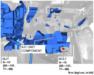
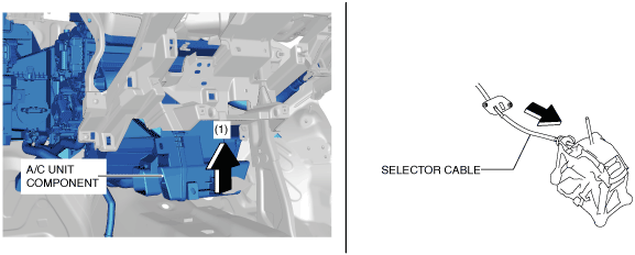
6. Remove the A/C unit component installation nut and bolt shown in the figure.
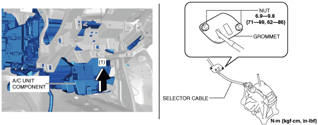
7. Remove the grommet installation nuts while lifting up A/C unit component in the direction of arrow (1).
8. Remove the selector cable while lifting up the A/C unit component in the direction of arrow (1).
9. Install in the reverse order of removal.
Selector Cable Adjustment
1. Disconnect the negative battery cable. (See NEGATIVE BATTERY CABLE DISCONNECTION/CONNECTION.)
2. Remove the center console tray. (See CENTER CONSOLE TRAY REMOVAL/INSTALLATION.)
3. Remove the shift bezel. (See SHIFT BEZEL REMOVAL/INSTALLATION.)
4. Remove the upper panel. (See UPPER PANEL REMOVAL/INSTALLATION.)
5. Remove the selector lever knob. (See Selector Lever Removal/Installation.)
6. Remove the shift panel. (See SHIFT PANEL REMOVAL/INSTALLATION.)
7. Shift the selector lever to the P position.
8. Pull out the safety lock in the direction of the arrow (1) shown in the figure, pull out the lock piece in the direction of the arrow (2) shown in the figure, and release the lock. (See Selector Cable (Selector Lever Side) Installation Note.)
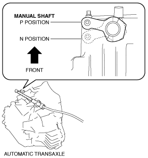
9. Set the manual shaft to the P position.
10. Press in the lock piece in the direction of the arrow (1) shown in the figure, press in the safety lock in the direction of the arrow (2) shown in the figure, and lock it.
11. Perform the procedure in the reverse order of Step 1 to 6 to install the removed part.
12. Perform the selector lever inspection. (See SELECTOR LEVER INSPECTION.)
Selector Cable (Selector Lever Side) Installation Note
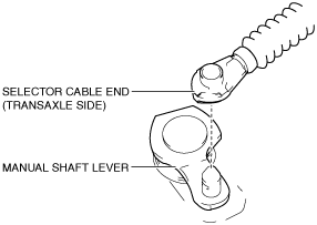
1. Verify that the selector lever is in the P position.
2. Verify that the manual shaft is in the P position.
3. Press in the lock piece in the direction of the arrow (1) shown in the figure, press in the safety lock in the direction of the arrow (2) shown in the figure, and lock it.
Selector Cable End (Transaxle Side) Installation Note
-
Caution
-
• Pull the clip within the range shown in the figure. If the clip is pulled excessively, it could deform and no longer function.
1. Install a clip to the groove of the selector cable end (transaxle side).
Cable Outer End (Transaxle Side) Installation Note
1. Assemble the cable outer end (transaxle side) to the bracket so that the marking is in the area of the arrow shown in the figure.