DOWN SWITCH INSPECTION [EW6A-EL]
id0517l2600600
Continuity Inspection
-
Note
-
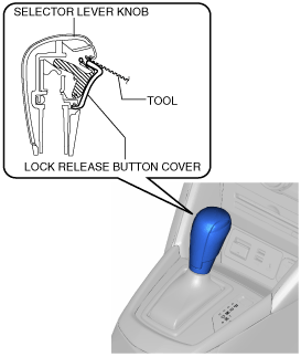
• The down switch is built into the selector lever component.
1. Disconnect the negative battery cable. (See NEGATIVE BATTERY CABLE DISCONNECTION/CONNECTION.)
2. Perform the following procedure to remove the selector lever knob.
-
Note
-
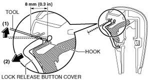
• If the servicing is difficult, release the shift lock manually and shift the selector lever to the N position.
- (1) Insert the tool (width: 4 mm {0.2 in} or less, thickness: 1 mm {0.04} or less) as shown in the figure.
-
- (2) Move the tool in the direction of arrow (1) in the figure and detach the hook. Move the lock release button cover in the direction of arrow (2) in the figure and remove it.
-
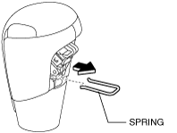
- (3) Remove the spring.
-
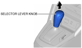
- (4) Remove the selector lever knob.
-
3. Remove the following parts:
- (1) Center console tray (See CENTER CONSOLE TRAY REMOVAL/INSTALLATION.)
- (2) Shift bezel (See SHIFT BEZEL REMOVAL/INSTALLATION.)
- (3) Upper panel (See UPPER PANEL REMOVAL/INSTALLATION.)
- (4) Shift panel (See SHIFT PANEL REMOVAL/INSTALLATION.)
- (5) Console side panel (See CONSOLE SIDE PANEL REMOVAL/INSTALLATION.)
- (6) Front console box (See FRONT CONSOLE BOX REMOVAL/INSTALLATION.)
- (7) CD player (with CD player) (See CD PLAYER REMOVAL.) (See CD PLAYER INSTALLATION.)
- (8) DVD/CD player (with DVD/CD player) (See DVD/CD PLAYER REMOVAL.) (See DVD/CD PLAYER INSTALLATION.)
- (9) Front console (See FRONT CONSOLE REMOVAL/INSTALLATION.)
- (10) Side wall (See SIDE WALL REMOVAL/INSTALLATION.)
- (11) Rear console (See REAR CONSOLE REMOVAL/INSTALLATION.)
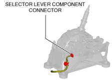
4. Disconnect the selector lever component connector.
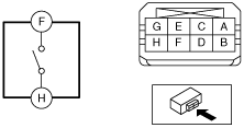
5. Verify that the continuity between selector lever component terminals F and H.
-
Down switch specification
|
Test condition
|
Continuity
|
|
Selector lever is in the M position (−) side position.
|
Continuity
|
|
Selector lever is not in the M position (−) side position.
|
No continuity
|