 |
am2zzw00007382
POWER BRAKE UNIT REMOVAL/INSTALLATION [L.H.D.]
id041100801850
1. Remove the following parts as a single unit. (See INTAKE-AIR SYSTEM REMOVAL/INSTALLATION [SKYACTIV-G 1.3, SKYACTIV-G 1.5].) (See INTAKE-AIR SYSTEM REMOVAL/INSTALLATION [SKYACTIV-D 1.5].)
2. Remove the battery and battery tray. (See BATTERY REMOVAL/INSTALLATION [SKYACTIV-G 1.3, SKYACTIV-G 1.5].) (See BATTERY REMOVAL/INSTALLATION [SKYACTIV-D 1.5].)
3. For the SKYACTIV-D 1.5 (i-ELOOP) vehicle, perform the following procedure.
4. Remove the following parts:
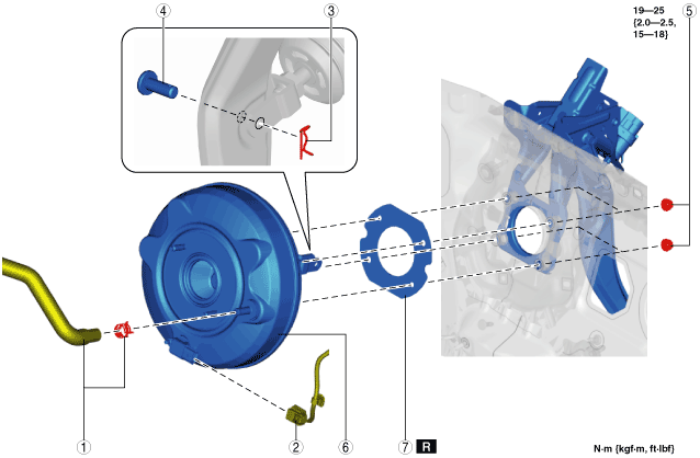
5. Remove in the order indicated in the table.
6. Install in the reverse order of removal.
7. After installation, add brake fluid, bleed the air, and inspect for fluid leakage. (See BRAKE FLUID AIR BLEEDING.)
8. Remove the brake switch. (See BRAKE PEDAL REMOVAL/INSTALLATION [L.H.D.].)
9. Inspect the brake pedal. (See BRAKE PEDAL INSPECTION.)
10. Install a new brake switch. (See BRAKE PEDAL REMOVAL/INSTALLATION [L.H.D.].)
am2zzw00007382
|
|
1
|
Vacuum hose, clamp
|
|
2
|
Power brake unit vacuum sensor connector (vehicles with i-stop)
|
|
3
|
Snap pin
(See Snap Pin Installation Note.)
|
|
4
|
Clevis pin
|
|
5
|
Nut
|
|
6
|
Power brake unit
|
|
7
|
Gasket
|
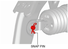
Snap Pin Installation Note
1. Install the snap pin as shown in the figure.
am2zzw00007419
|