MANUAL TRANSAXLE SHIFT MECHANISM REMOVAL/INSTALLATION [F66M-R]
id0516n2160800
1. Disconnect the negative battery cable. (See NEGATIVE BATTERY CABLE DISCONNECTION/CONNECTION.)
2. Remove the shift lever using the following procedure:
- (1) Remove the center console tray. (See CENTER CONSOLE TRAY REMOVAL/INSTALLATION.)
-
- (2) Remove the shift bezel. (See SHIFT BEZEL REMOVAL/INSTALLATION.)
-
- (3) Remove the upper panel. (See UPPER PANEL REMOVAL/INSTALLATION.)
-
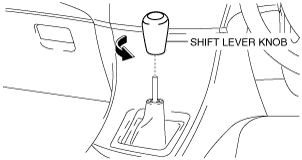
- (4) Remove the shift lever knob.
-
- (5) Remove the shift panel. (See SHIFT PANEL REMOVAL/INSTALLATION.)
-
- (6) Remove the console side panel. (See CONSOLE SIDE PANEL REMOVAL/INSTALLATION.)
-
- (7) Remove the front console box. (See FRONT CONSOLE REMOVAL/INSTALLATION.)
-
- (8) Remove the CD player. (with CD player) (See CD PLAYER REMOVAL.) (See CD PLAYER INSTALLATION.)
-
- (9) Remove the DVD/CD player. (with DVD/CD player.) (See DVD/CD PLAYER REMOVAL) (See DVD/CD PLAYER INSTALLATION.)
-
- (10) Remove the front console. (See FRONT CONSOLE REMOVAL/INSTALLATION.)
-
- (11) Remove the side wall. (See SIDE WALL REMOVAL/INSTALLATION.)
-
- (12) Remove the rear console. (See REAR CONSOLE REMOVAL/INSTALLATION.)
-
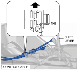
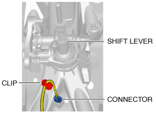
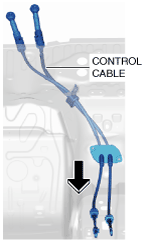
- (13) Press the tabs on the control cable as shown in the figure and disconnect the control cable from the shift lever.
-
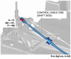
- (14) Disconnect the console cable end (shift side) from the shaft lever.
-
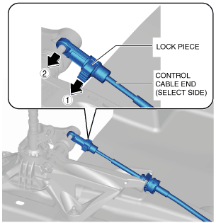
- (15) Disconnect the control cable end (select side) from the shift lever using the following procedure:
-
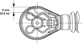
- 1) Push out the lock piece in the direction shown in the figure.
-
- 2) Disconnect the control cable end (select side) from the shift lever.
-
- (16) Disconnect the connector from the shift lever as shown in the figure.
-
- (17) Remove the shift lever.
-
3. Remove the control cable using the following procedure: (with SKYACTIV-G 1.5)
- (1) Remove the air cleaner, air hose and fresh air duct as a single unit. (See INTAKE-AIR SYSTEM REMOVAL/INSTALLATION [SKYACTIV-G 1.3, SKYACTIV-G 1.5].)
-
- (2) Remove the battery tray and PCM component. (See BATTERY REMOVAL/INSTALLATION [SKYACTIV-G 1.3, SKYACTIV-G 1.5].)
-
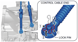
- (3) Disconnect the control cable ends from the manual transaxle using the following procedure. (See Control Cable End Installation Note.)
-
-
Caution
-
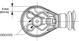
• Pull the lock pin within the range shown in the figure. If the lock pin is pulled excessively, it could deform and no longer function.
- 1) Pull the lock pin in the direction of the arrow shown in the figure and release the control cable ends (manual transaxle side) lock.
-
- 2) Disconnect the control cable ends from the manual transaxle.
-
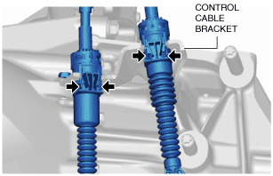
- (4) Press the tabs on the control cable and disconnect the control cable from the control cable bracket.
-
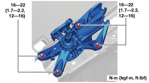
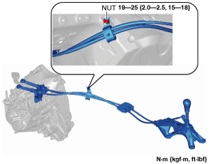
- (5) Remove the fastening nut for the control cable.
-
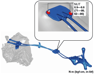
- (6) Remove the fastening nuts for the grommet.
-
- (7) Remove the control cable.
-
4. Remove the control cable using the following procedure: (with SKYACTIV-D 1.5)
- (1) Remove the battery and battery tray. (See BATTERY REMOVAL/INSTALLATION [SKYACTIV-D 1.5].)
-
- (2) Remove the DC-DC converter. (with i-ELOOP) (See DC-DC CONVERTER (i-ELOOP) REMOVAL/INSTALLATION [WITH i-ELOOP (SKYACTIV-D 1.5)].)
-
- (3) Disconnect the control cable ends from the manual transaxle using the following procedure. (See Control Cable End Installation Note.)
-
-
Caution
-
• Pull the lock pin within the range shown in the figure. If the lock pin is pulled excessively, it could deform and no longer function.
- 1) Pull the lock pin in the direction of the arrow shown in the figure and release the control cable ends (manual transaxle side) lock.
-
- 2) Disconnect the control cable ends from the manual transaxle.
-
- (4) Press the tabs on the control cable and disconnect the control cable from the control cable bracket.
-
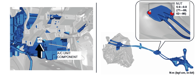
- (5) Remove the fastening nut for the control cable.
-
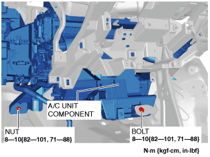
- (6) Remove the A/C unit component installation nut and bolt shown in the figure.
-
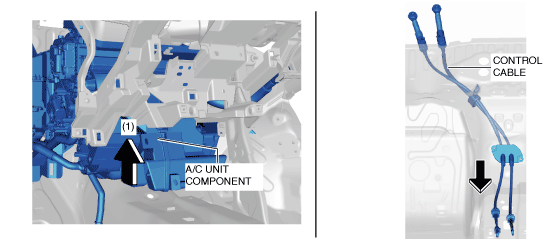
- (7) Remove the grommet installation nuts while lifting up A/C unit component in the direction of arrow (1).
-
- (8) Remove the control cable while lifting up the A/C unit component in the direction of arrow (1).
-
5. Make sure that the shift lever (transaxle side) is in neutral position.
6. Install in the reverse order of removal.
Control Cable End Installation Note
-
Caution
-
• Pull the lock pin within the range shown in the figure. If the lock pin is pulled excessively, it could deform and no longer function.
1. Install the lock pin to the groove of the control cable end.
2. Connect the control cable end to the manual transaxle.