 |
am2zzw00011611
REAR WASHER HOSE REMOVAL/INSTALLATION
id091900801600
Rear Washer Hose A
1. Remove the front mudguard (RH). (See MUDGUARD REMOVAL/INSTALLATION.)
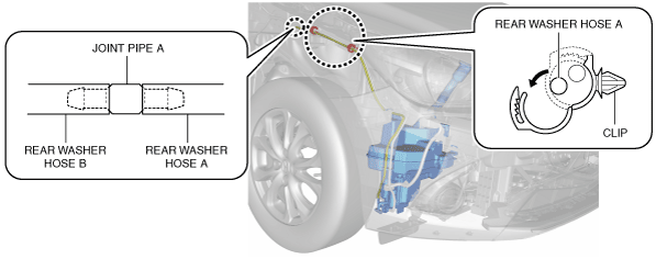
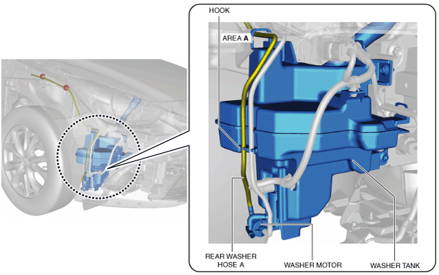
2. Disconnect rear washer hose A from the washer motor.
am2zzw00011611
|
3. Remove rear washer hose A from washer tank hook. (See Rear washer hose A installation note.)
4. Pull out rear washer hose A from area A of the washer tank.
5. Remove rear washer hose A from the clip.
am2zzw00011612
|
6. Disconnect rear washer hose B from joint pipe A.
7. Remove rear washer hose A.
8. Install in the reverse order of removal.
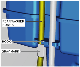
Rear washer hose A installation note
1. When installing rear washer hose A to the washer tank hook, install it with the upper end of the gray mark aligned to the hook.
am2zzw00011613
|
Rear Washer Hose B
1. Remove the front mudguard (RH). (See MUDGUARD REMOVAL/INSTALLATION.)
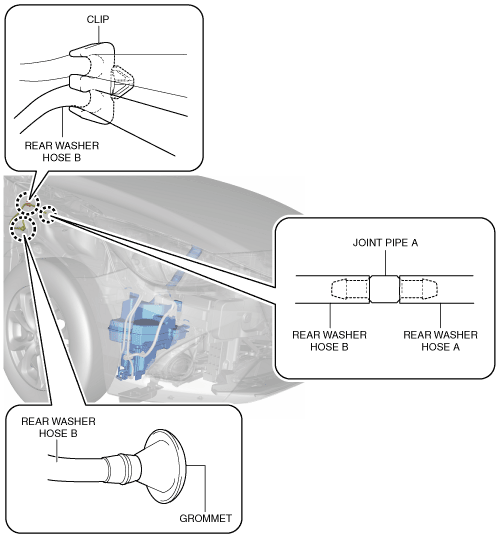
2. Disconnect rear washer hose B from joint pipe A.
am2zzw00011614
|
3. Remove rear washer hose B from the clip.
4. Disconnect the negative battery cable. (See NEGATIVE BATTERY CABLE DISCONNECTION/CONNECTION.)
5. Remove the following parts:
6. Remove the grommet from the body.
am2zzw00011615
|
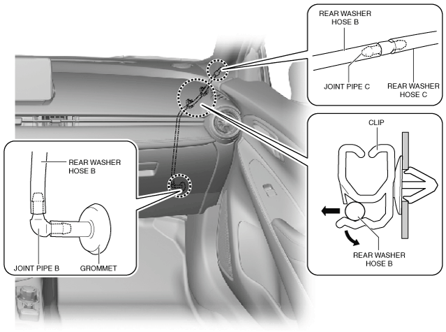
7. Remove rear washer hose B from clips.
8. Disconnect rear washer hose C from joint pipe C.
9. Remove rear washer hose B.
10. Install in the reverse order of removal.
Rear Washer Hose C
1. Disconnect the negative battery cable. (See NEGATIVE BATTERY CABLE DISCONNECTION/CONNECTION.)
2. Remove the following parts:
3. Remove the tape.
am2zzw00011616
|
4. Remove rear washer hose C. (See Rear washer hose C installation note.)
5. Install in the reverse order of removal.
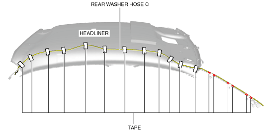
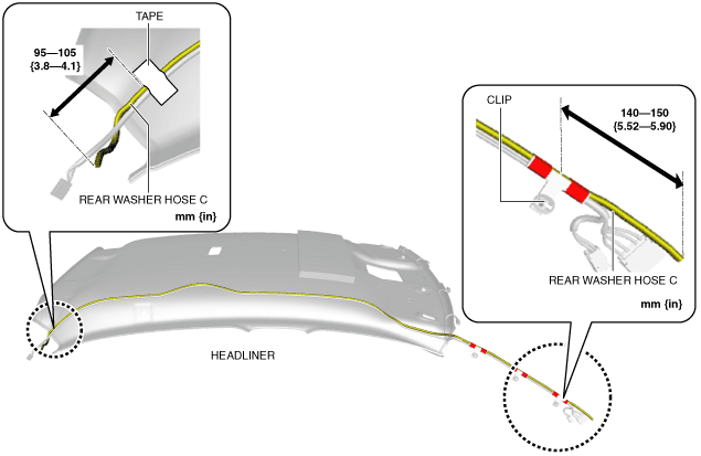
Rear washer hose C installation note
1. When installing rear washer hose C to the headliner, install it aligning to the position shown in the figure.
am2zzw00011617
|
Rear Washer Hose D
1. Disconnect the negative battery cable. (See NEGATIVE BATTERY CABLE DISCONNECTION/CONNECTION.)
2. Remove the following parts:
3. Peel back the trunk side trim and remove the C-pillar trim. (See C-PILLAR TRIM REMOVAL/INSTALLATION.)
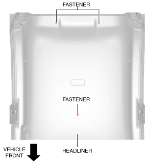
4. Remove the fasteners.
am2zzw00011618
|
5. Peel back the seaming welt of the rear door and the liftgate.
6. Partially peel back the headliner.
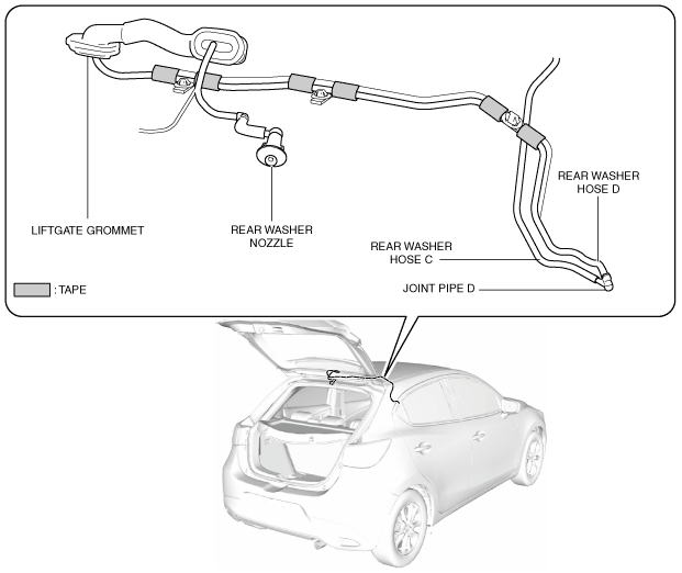
7. Disconnect rear washer hose C from joint pipe D.
am2zzw00011619
|
8. Remove the tape.
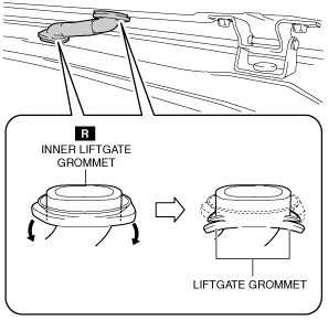
9. Partially peel the liftgate grommet.
am2zzw00011620
|
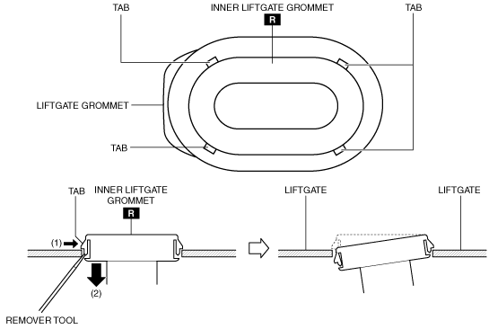
10. While pressing the tabs of the inner liftgate grommet in the direction of arrow (1) shown in the figure, pull the inner liftgate grommet in the direction of arrow (2) and detach the tabs of the inner liftgate grommet from the liftgate.
am2zzw00011621
|
11. Detach all the tabs of the inner liftgate grommet from the liftgate and remove the inner liftgate grommet.
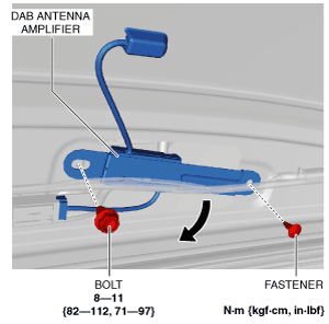
12. Remove the bolt (with DAB antenna amplifier).
am2zzw00011622
|
13. Remove the fastener (with DAB antenna amplifier).
14. Set the DAB antenna amplifier aside in the direction of the arrow shown in the figure. (with DAB antenna amplifier).
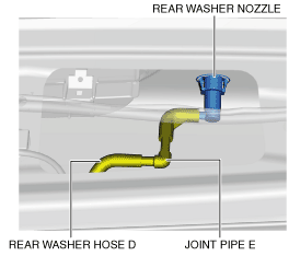
15. Disconnect rear washer hose D from joint pipe E.
am2zzw00011623
|
16. Remove rear washer hose D.
17. Install in the reverse order of removal.